Pressure adjuster

A technology for pressure regulators and adjusting handles, applied to valve details, safety valves, engine components, etc., can solve problems such as poor reliability, increased production costs, and complex structure of pressure regulators, and achieve stable pressure and stable gas pressure Effect

Inactive Publication Date: 2020-01-14
徐州鸿业仪器仪表有限公司
View PDF0 Cites 1 Cited by
  • Summary
  • Abstract
  • Description
  • Claims
  • Application Information

AI Technical Summary

Problems solved by technology

[0004] The pressure regulator in the prior art has a complex structure, which is not convenient for installation and maintenance. At the same time, its manufacturing cost is high,

Method used


Image

  • Pressure adjuster
  • Pressure adjuster
  • Pressure adjuster

Examples


Example Embodiment

[0030] The present invention will be further described below in conjunction with accompanying drawing.

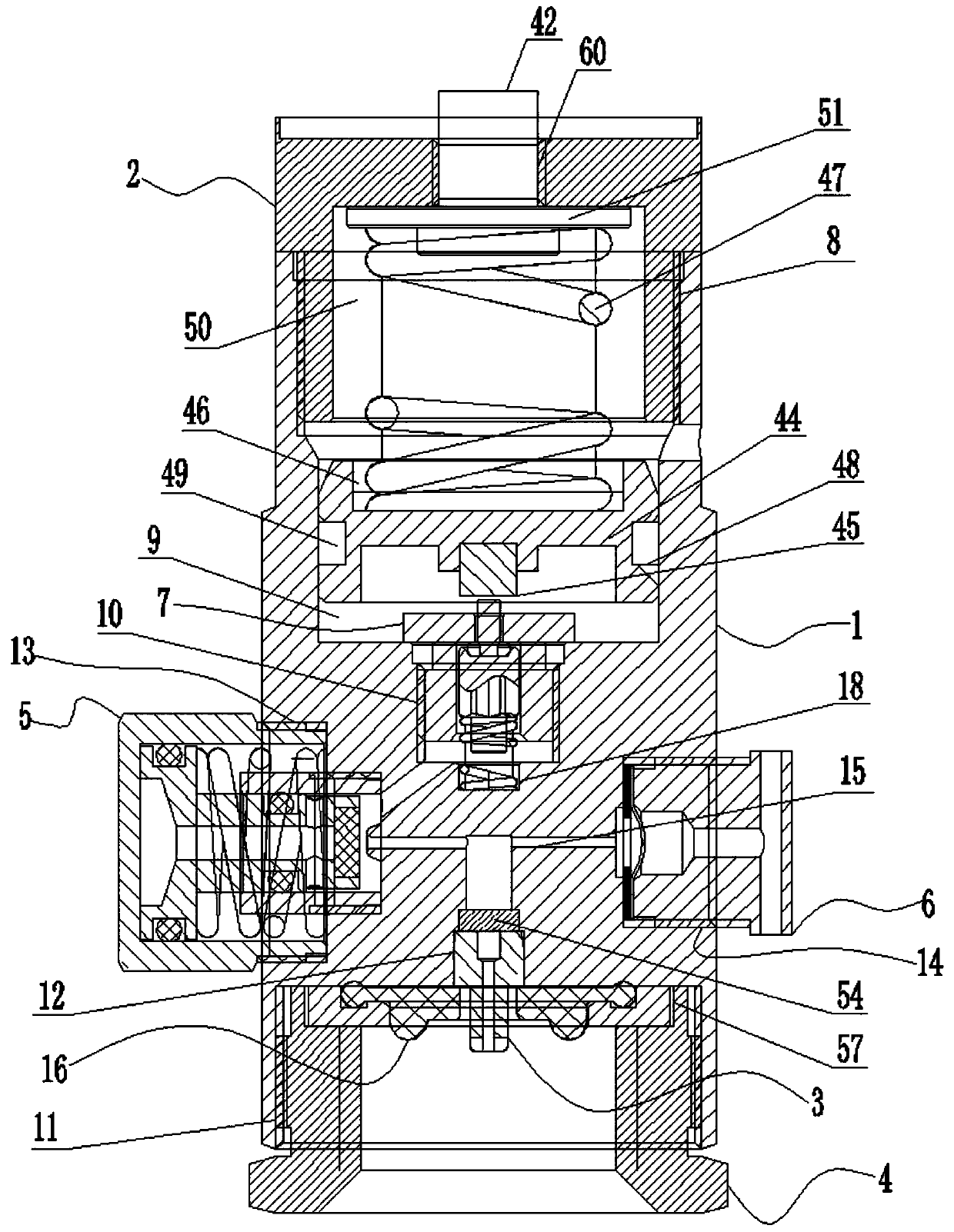
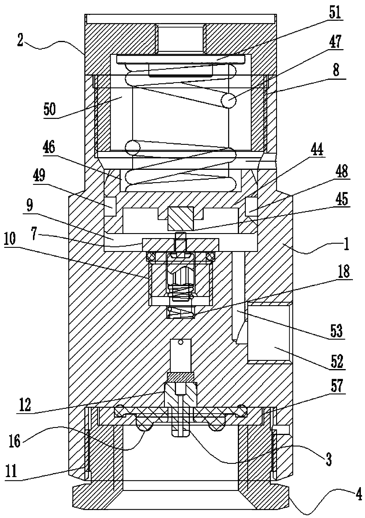
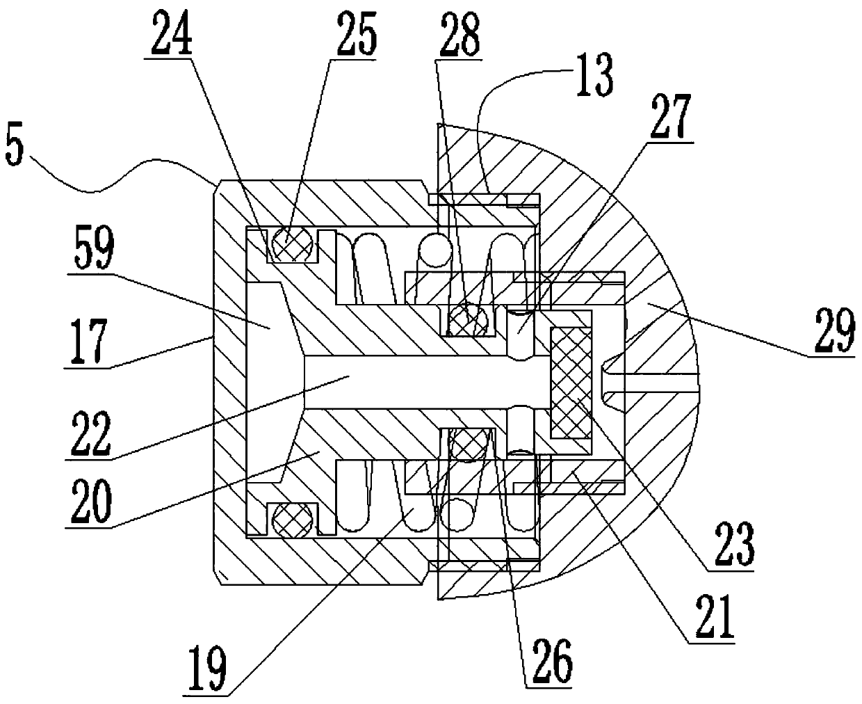
[0031] like Figure 1 to Figure 6 As shown, a pressure regulator includes a valve body 1, an adjusting handle 2, an air inlet nozzle 3, an air inlet nut 4, a primary pressure stabilizing component 5, a safety valve component 6, a secondary pressure stabilizing component 7, and a lower spring seat 44. Pressure regulating spring C47;

[0032] The upper part of the valve body 1 is provided with an upper installation cavity 8, a ventilation cavity 9, a middle installation cavity A10, and a spring cavity A18 with gradually decreasing inner diameters from top to bottom at the axial center, and the lower part of the valve body 1 is on its axis. The center is provided with a lower installation chamber 11 and a middle installation chamber B12 with gradually decreasing inner diameters in sequence from bottom to top, and the upper installation chamber 8 and the middle installation ch...


PUM


Abstract

The invention discloses a pressure adjuster. An adjusting handle is arranged at the top of an upper cavity of a valve body; a second-stage voltage stabilizing module is arranged under the adjusting handle; an upper spring base, an adjusting spring C and a lower spring base are arranged between the adjusting handle and the second-stage voltage stabilizing module in sequence; a pressing block in abutting fit with a valve rod at the upper end of the second-stage voltage stabilizing module is arranged in the lower end center of the lower spring base; a first-stage voltage stabilizing module and asafety valve module are assembled in cavities on the two sides of the valve body, and communicate through a communicating channel A; an intake nut is assembled in a cavity at the lower part of the valve body through threaded fit; an intake mouth is assembled in the center in the intake nut, and communicates with the communicating channel A; the first-stage voltage stabilizing module and the second-stage voltage stabilizing module communicate through a communicating channel B; and an exhaust port of the second-stage voltage stabilizing module communicates with an exhaust port on the surface ofthe valve body through an exhaust channel. The adjuster is simple in structure, excellent in voltage stabilization performance, convenient to install and maintain, small in size, low in weight and convenient to carry.

Description

technical field [0001] The invention relates to the technical field of voltage stabilization control, in particular to a pressure regulator. Background technique [0002] The pressure regulator is a device that can keep the output pressure within a stable pressure range. It is suitable for precision instruments and pneumatic control fields, and provides stable pressure input for precision equipment. [0003] Most of the existing pressure regulators include a high-pressure chamber and a low-pressure chamber, and use the force balance principle to control the movement of the valve assembly used to control the output pressure. When an output pressure is given to the regulator, the downward force of the pressure regulating spring pushes the diaphragm The component pushes down, and the pressure regulator valve opens; when the output pressure value is reached, the downward force exerted by the pressure regulator spring on the diaphragm component and the upward force exerted by the...

Claims


Application Information

Patent Timeline
IPC IPC(8): F16K17/40F16K31/60
CPCF16K17/403F16K31/60
Inventor 刘倩王航李汶汶宗鹏举
Owner 徐州鸿业仪器仪表有限公司
Why Eureka
Try Eureka