Fixing device for micro-drop detection chip

A technology for detecting chips and fixing devices, applied in the directions of laboratory utensils, supporting utensils, laboratory containers, etc., can solve the problems of alignment error, detection signal value change, exceeding the detection focal length range of the instrument, etc., and achieve the sealing effect. Uniformity, stable test results, and uniform sealing force

Pending Publication Date: 2020-01-17
TARGETINGONE TECH (BEIJING) CORP
View PDF0 Cites 2 Cited by
  • Summary
  • Abstract
  • Description
  • Claims
  • Application Information

AI Technical Summary

Problems solved by technology

Due to the matching gap between the positioning of the column hole and the positioning of the edge, and the deformability of the flexible gasket, the clamping force cannot completely limit the lateral movement of the chip, which is easy to cause errors in the alignment of the micro-droplet detection chip and the detection mechanism.
In the rigid chip fixing device, due to the errors in the chip processing process, the flatness of the planes at different micro-droplet detection windows is inconsistent or even exceeds the detection focal length range of the instrument, which directly leads to changes in the detection signal value

Method used


Image

  • Fixing device for micro-drop detection chip
  • Fixing device for micro-drop detection chip
  • Fixing device for micro-drop detection chip

Examples


Embodiment Construction

[0029] In order to enable those skilled in the art to better understand the technical solutions in the application, the present invention will be further described below in conjunction with the following examples. Obviously, the described embodiments are only a part of the embodiments of the application, rather than all Example. Based on the embodiments in this application, all other embodiments obtained by persons of ordinary skill in the art without making creative efforts shall fall within the scope of protection of this application. The present invention will be further described below in conjunction with the accompanying drawings and embodiments.

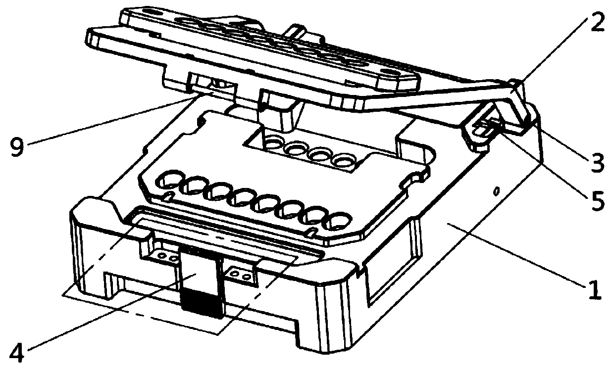
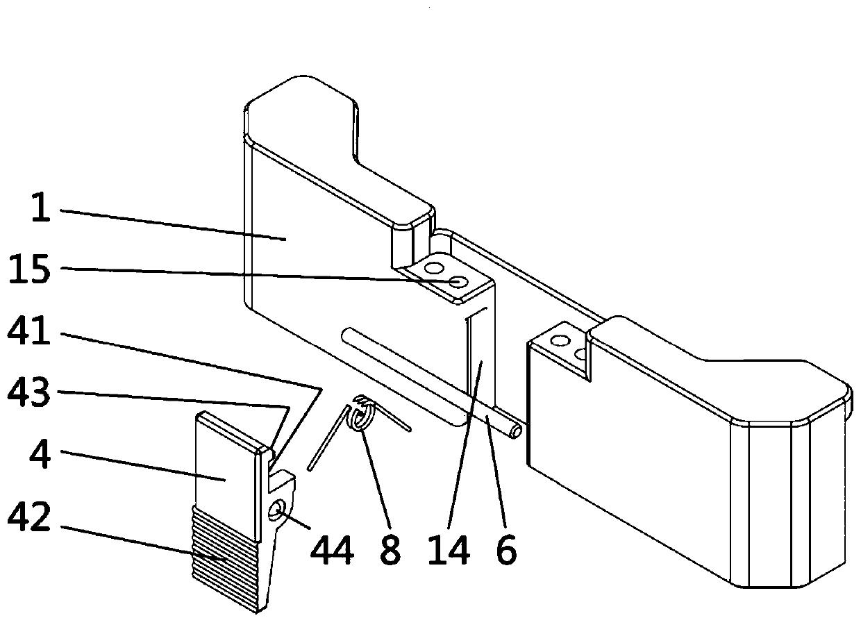
[0030] Such as figure 1 and 2 As shown, the practical micro-droplet detection chip fixing device includes a rigid bottom plate 1 and a rigid flip cover 2, and the rear ends of the two are connected by a rotating shaft 3 to form a rotating pair. The bottom plate 1 is used to accommodate the micro-droplet detection chip; the b...


PUM


Abstract

The invention provides a fixing device for a micro-drop detection chip. The fixing device comprises a rigid bottom plate and a rigid flip cover, and the rear ends of the rigid bottom plate and the rigid flip cover are connected through a rotating shaft to form a rotating pair; the bottom plate is used for accommodating the micro-drop detection chip, and the bottom plate and the flip cover are matched to realize rigid clamping of the micro-drop detection chip; when the micro-drop detection chip is detected, a connecting pipe comprising at least two detection pipes is placed, a groove for accommodating the micro-drop detection chip is arranged on the bottom plate, and an elastic device is arranged at the bottom of each groove for eliminating bottom tolerance for accommodating the micro-dropdetection chip. The elastic device is additionally arranged at the bottom of each pipe of the connecting pipe, so that the overall tolerance between the connecting pipe and the chip plane can be compensated, the sealing force is more uniform, the sealing effect is more uniform, the flow of liquid in all flow channels of the chip is more uniform, and the detection result of the whole instrument ismore stable.

Description

technical field [0001] The invention relates to the field of microfluidic chips, in particular to a micro-droplet detection chip fixing device. Background technique [0002] The size of the channel structure of the micro-droplet detection chip is generally in the range of 10-100 μm. In order to detect the contents of the micro-droplet, the micro-droplet detection chip needs to be positioned and clamped. At present, the commonly used microfluidic chip positioning methods are mainly column hole positioning and edge positioning. The clamping method mainly relies on the flexible gasket between the clamp and the microfluidic chip to provide a clamping force perpendicular to the chip surface. Since there is a matching gap between the positioning of the column hole and the positioning of the edge, and the deformability of the flexible gasket makes the clamping force unable to completely limit the lateral movement of the chip, it is easy to cause errors in the alignment of the micr...

Claims


Application Information

Patent Timeline
Patent Type & Authority Applications(China)
IPC IPC(8): B01L3/00B01L9/00
CPCB01L3/5027B01L9/527
Inventor 黄海旺白宇梁欢迎荆高山郭永杨文军
Owner TARGETINGONE TECH (BEIJING) CORP
Why Eureka
Try Eureka