A feed mixing and crushing processing system

A mixing and crushing and processing system technology, which is applied in the direction of feed, mixer, mixer with rotating stirring device, etc., can solve the problems that the feed cannot be crushed repeatedly, the crushing effect is not complete, and the feed does not have the function of stirring.

Active Publication Date: 2021-02-26
ZHENGZHOU BARY ANIMAL PHARMA
View PDF9 Cites 0 Cited by
  • Summary
  • Abstract
  • Description
  • Claims
  • Application Information

AI Technical Summary

Problems solved by technology

However, this device cannot repeatedly crush the feed, and it does not have the function of stirring the feed, so it is prone to incomplete crushing effect.

Method used


Image

  • A feed mixing and crushing processing system
  • A feed mixing and crushing processing system
  • A feed mixing and crushing processing system

Examples


specific Embodiment approach 1

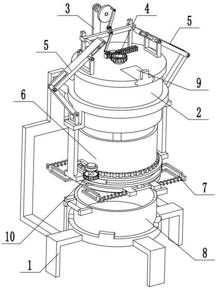
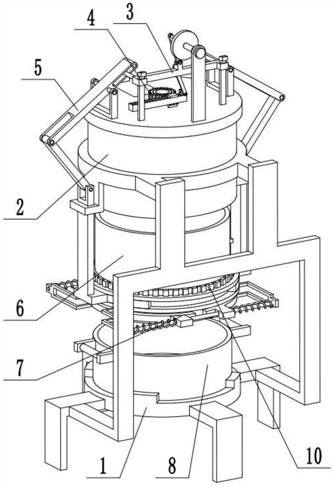
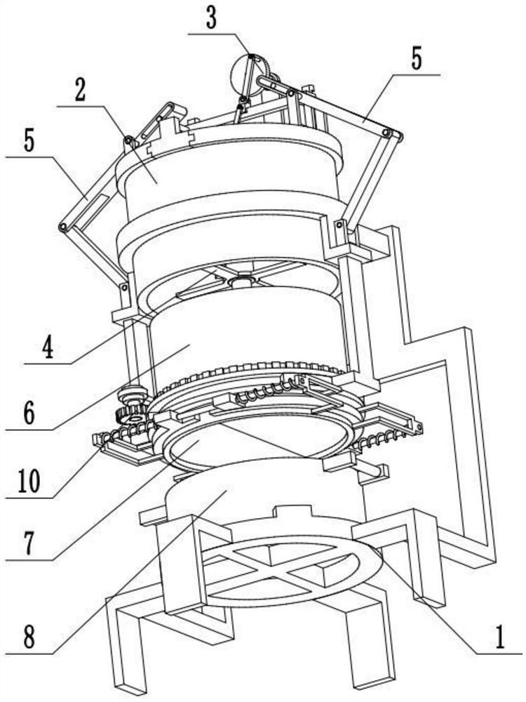
[0033] Combine below Figure 1-14 Describe this embodiment, a feed mixing and crushing processing system, including a support frame body 1, a grinder fixing seat 2, a power output device 3, a feed grinder 4, a reciprocating control member 5, a feed container 6, a bottom material plate 7, Feed basin 8, retaining cover 9 and rotating member 10, described pulverizer holder 2 is fixedly connected on the upper end of support frame body 1, power output device 3 is fixedly connected on pulverizer holder 2, and feed pulverizer 4 is arranged on On the pulverizer fixing seat 2, the feed pulverizer 4 is connected to the power output device 3 through transmission, and there are two reciprocating control parts 5, and the two reciprocating control parts 5 are symmetrically arranged on the left and right sides of the pulverizer fixing seat 2, and the two reciprocating control parts 5 are symmetrically arranged on the left and right sides of the pulverizer fixing seat 2, and the two reciprocatin...

specific Embodiment approach 2

[0035] Combine below Figure 1-14 To illustrate this embodiment, the support frame body 1 includes a feed pot placement seat 1-1, a support foot 1-2, a connecting frame 1-3 and a stopper 1-4; the feed pot placement seat 1-1 is evenly arranged around Four supporting feet 1-2, the connecting frame 1-3 are fixedly connected on the left and right supporting feet 1-2, the feed basin is placed on the seat 1-1 and surrounded by four stoppers 1-4, and the feed basin 8 is placed on The feed basin is placed on the seat 1-1, and the feed basin 8 is positioned between four blocks 1-4. Four stoppers 1-4 limit the feed basin 8 to move on the feed basin placement seat 1-1, and the feed basin 8 can be taken out after upwardly lifting the feed basin 8 and breaking away from the four stoppers 1-4.

specific Embodiment approach 3

[0037] Combine below Figure 1-14 To illustrate this embodiment, the pulverizer holder 2 includes a cylinder 2-1, a cylinder holder 2-2, a fixed sliding sleeve 2-3, a top cover 2-4 and a cover chute 2-5; the cylinder 2-1 is fixedly connected to the tube fixing seat 2-2, the tube fixing seat 2-2 is fixedly connected to the connecting frame 1-3, and the two ends of the tube fixing seat 2-2 are respectively fixedly connected to a fixed sliding sleeve 2-3, The upper end of the cylinder 2-1 is fixedly connected to the top cover 2-4, and the front end of the top cover 2-4 is provided with a cover chute 2-5, and the cover chute 2-5 communicates with the inside of the cylinder 2-1, and the cover chute 9 interference fits are connected in the blocking cover chute 2-5. After pulling away from the retaining cover 9, feed is put into the cylinder 2-1, and the feed falls into the retaining cover 9, and the retaining cover 9 is reset and closed after throwing in.


PUM


Abstract

The invention relates to a feed mixing and crushing processing system, which relates to the technical field of feed processing, and includes a support frame body, a grinder fixing seat, a power output device, a feed grinder, a reciprocating control part, a feed container, a bottom material plate, a feed basin, and a stopper. The beneficial technical effect of the cover and the rotating part is that the invention can repeatedly crush the feed, and at the same time, it can stir the feed, so that the feed is crushed more fully and the crushing effect is thorough; the phenomenon of feed blockage does not occur. The pulverizer fixing seat is fixedly connected to the upper end of the support frame body, the power output device is fixedly connected to the pulverizer fixing seat, the feed pulverizer is set on the pulverizer fixing seat, the feed pulverizer is connected to the power output device in transmission, and the reciprocating control part is set There are two, and two reciprocating control parts are symmetrically arranged on the left and right sides of the pulverizer fixing seat, and the two reciprocating control parts are all connected with the power output device, and the feed container is arranged on the two reciprocating control parts.

Description

technical field [0001] The invention relates to the technical field of feed processing, in particular to a feed mixing and crushing processing system. Background technique [0002] The existing patent number is CN201910173094.5 and a pulverizer for feed processing. The invention discloses a pulverizer for feed processing, including a pulverizer body. A first pulverization chamber is arranged in the pulverizer body. A stirring motor is installed on one side of the first crushing room, the output end of the stirring motor is connected to a first rotating shaft, and the first rotating shaft leads into the first crushing chamber, and a first blade is installed on the first rotating shaft , the bottom of the first crushing chamber is provided with a screen, the side of the first crushing chamber is provided with a feeding hopper, and a discharge port is left on the bottom of the end of the feeding hopper close to the first rotating motor. The bottom of the feed opening is provid...

Claims


Application Information

Patent Timeline
Patent Type & Authority Patents(China)
IPC IPC(8): B02C18/10B02C18/16A23N17/00B01F7/18
CPCB02C18/10B02C18/16A23N17/00A23N17/007B01F27/90
Inventor 孟宇
Owner ZHENGZHOU BARY ANIMAL PHARMA
Why Eureka
Try Eureka