Check patentability & draft patents in minutes with Patsnap Eureka AI!

Continuous casting vibrating support roller with built-in eccentric rotating mechanism

A technology of eccentric rotation and support roller, applied in the field of metal solidification and continuous casting, can solve the problem of no equipment structure plan, and achieve the effect of easy maintenance

Pending Publication Date: 2020-01-17
ZHONG NAT ENG & RES CENT
View PDF3 Cites 0 Cited by
  • Summary
  • Abstract
  • Description
  • Claims
  • Application Information

AI Technical Summary

Problems solved by technology

However, the above-mentioned patents only provide technical ideas, and do not provide a device structure solution for realizing the above-mentioned functions.

Method used


Image

  • Continuous casting vibrating support roller with built-in eccentric rotating mechanism
  • Continuous casting vibrating support roller with built-in eccentric rotating mechanism
  • Continuous casting vibrating support roller with built-in eccentric rotating mechanism

Examples


Embodiment 1

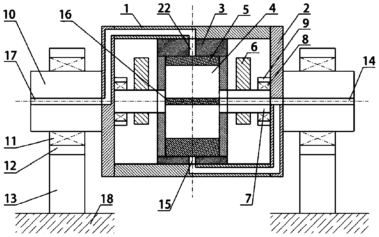
[0067] Example 1 - Continuous casting vibrating support roll with built-in eccentric rotation device (single rotor)

[0068] see figure 1 , it mainly includes: vibration support roller body 1, end covers 2 on both sides, rotor shell 3, rotor 4, movable blade 5, eccentric block 6, rotor rotating shaft 7, rotor rotating shaft bearing 8, rotor rotating shaft bearing Seat 9, rotating shaft 10, bearing 11, bearing seat 12, elastic support seat 13, air intake channel 14 (including: radial air intake hole 15, central air intake groove 16), air outlet channel 17, base stand 18 and so on. During use, the vibrating support roll body 1 is in contact with the casting strand 19 and rotates with the movement of the casting strand.

[0069] Structurally, the vibrating support roller body 1 is mechanically connected to the end covers 2 on both sides (such as bolts, pins, etc.) to facilitate disassembly and maintenance. The end cover 2 can be connected with the rotor rotating shaft bearin...

Embodiment 2

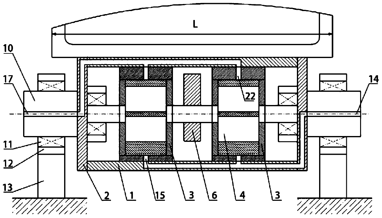
[0075] Example 2 - Vibrating support rolls for continuous casting (multiple rotors) with built-in eccentric rotation

[0076] In the present invention, there may be multiple rotor housings 3, rotors 4, etc., to drive an eccentric block 6 to rotate, see figure 2 .

Embodiment 3

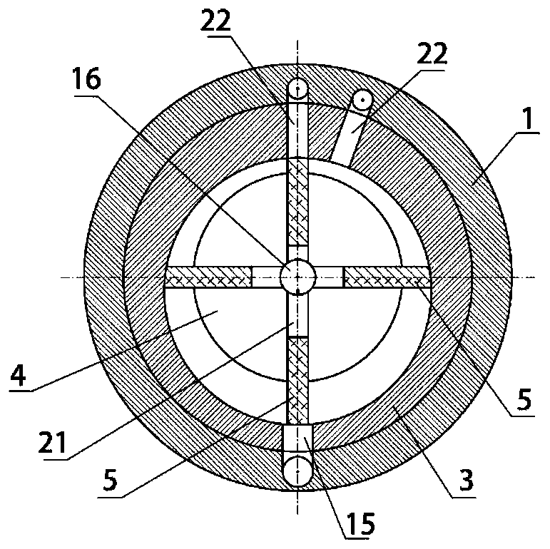
[0077] Example 3 - The rotor is a fixed blade

[0078] The present invention can also be a fixed blade, that is, the axial flow blade 20, and the axial flow is on the rotor 4. At this time, the rotor housing 3 may not be needed; the compressed air flows in from one side and flows out from the other side to pass through the axial flow blade 20 promote the eccentric block 6 to rotate, see Figure 4 .

[0079] In use, at the same cross-sectional position of the slab, the vibrating support roller can be placed on one side of the slab, or can be placed on symmetrical two or more sides of the sub-slab, as shown in Fig. 6 .

[0080] The shape of vibrating support roll roll body 1 section can be rectangular, see figure 1 , can also be trapezoidal, stepped, circular, convex arc, concave arc or not limited to the above-mentioned shapes, see FIG. 7 .

[0081] When in use, the vibrating support roll can be placed at the lower end of the mold outlet of the continuous casting machine, ...


PUM

PropertyMeasurementUnit
diameteraaaaaaaaaa

Abstract

The invention relates to the field of metal solidification and continuous casting, in particular to a continuous casting vibrating support roller with a built-in eccentric rotating mechanism. The continuous casting vibrating support roller comprises a vibrating support roller body (1), outer rotating shafts (10), outer bearing seats (12), support seats (13) and base stands (18); the continuous casting vibrating support roller further comprises the eccentric rotating mechanism arranged in the vibrating support roller body (1); the eccentric rotating mechanism includes an inner rotating shaft (7), and at least one rotor driving part and at least one eccentric block (6) which are arranged on the inner rotating shaft (7); and the at least one rotor driving part is driven by a fluid power source to rotate to drive the inner rotating shaft (7) to rapidly rotate at a speed higher than the rotating speed of the vibrating support roller body (1), and the at least one eccentric block (6) is driven to rotate and generate controllable vibration, so that vibration perpendicular to a blank shell of a casting blank (19) is generated by the vibrating support roller body (1), and the blank shell ofthe casting blank (19) is subjected to a force and vibrates.

Description

technical field [0001] The invention relates to the fields of metal solidification and continuous casting, in particular to a continuous casting vibration support roll with a built-in eccentric rotation mechanism. Background technique [0002] With the development of metallurgical technology in the world, modern continuous casting technology continues to improve, and the types of castable steel continue to expand. Some high-alloy, high-quality special steels have been continuously produced in the continuous casting production process of large iron and steel enterprises. In order to solve the problems of solidification segregation and shrinkage cavity defects of special steel, metallurgical scientific and technological workers have developed many patents and technologies in this technology for a long time. At present, there are mainly electromagnetic stirring technology and soft pressing or casting and rolling technology at the end of solidification that are widely used in in...

Claims


Application Information

Patent Timeline
Patent Type & Authority Applications(China)
IPC IPC(8): B22D11/128
CPCB22D11/1287
Inventor 张慧王明林干勇
Owner ZHONG NAT ENG & RES CENT
Features
  • R&D
  • Intellectual Property
  • Life Sciences
  • Materials
  • Tech Scout
  • Unparalleled Data Quality
  • Higher Quality Content
  • 60% Fewer Hallucinations
Learn More