
Three-jaw chuck

A three-jaw chuck and chuck technology, which is applied in the field of mechanical processing, can solve problems such as poor stability and small clamping force of jaws, and achieve the effect of increasing clamping force and clamping stability

Active Publication Date: 2020-01-17
诸暨市港灵科技有限公司
View PDF7 Cites 3 Cited by
  • Summary
  • Abstract
  • Description
  • Claims
  • Application Information

AI Technical Summary

Problems solved by technology

[0004] When the existing three-jaw chuck is in use, especially when clamping some parts with special shapes, for example: the processed part is a cylinder and the clamping position of the cylinder is a stepped structure, and then the cylindrical body with a stepped structure When clamping, because the clamping surface of the claw is flat, the clamping force of the claw is too small when clamping the stepped cylinder, and the clamping stability is poor.

Method used


Image

  • Three-jaw chuck
  • Three-jaw chuck
  • Three-jaw chuck

Examples


Embodiment Construction

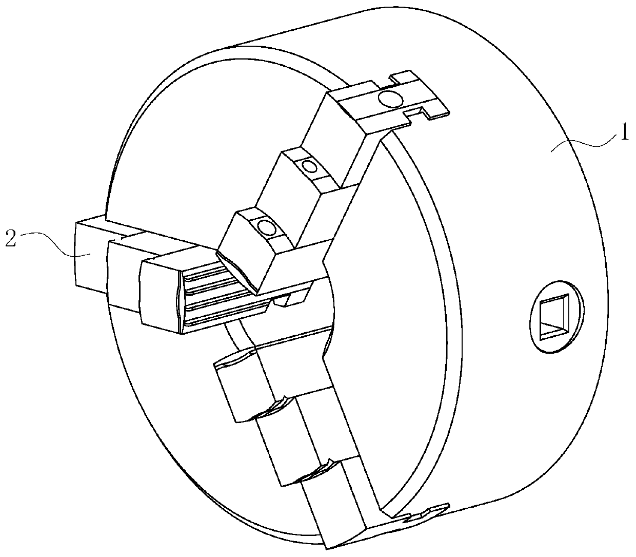
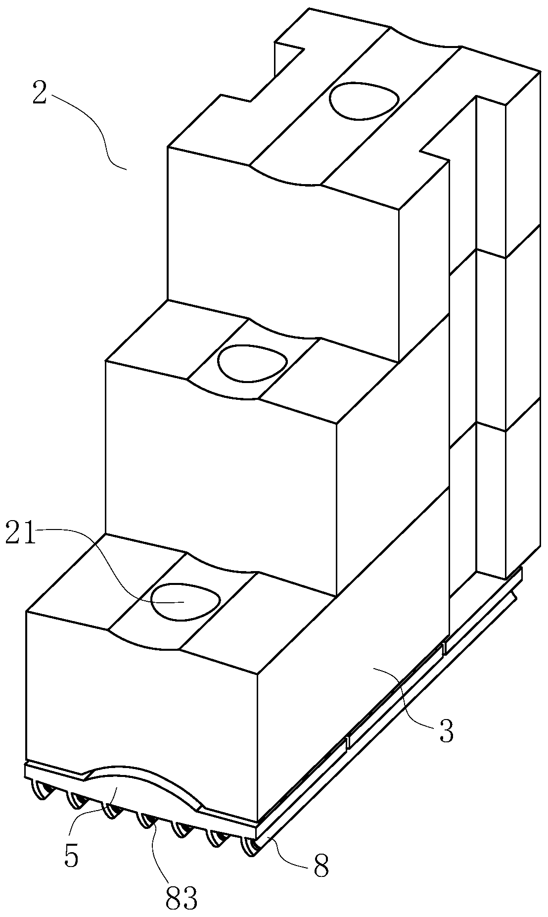
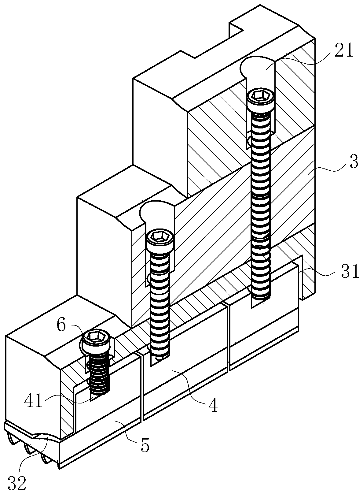
[0022] use Figure 1-Figure 5 A three-jaw chuck according to an embodiment of the present invention will be described as follows.

[0023] Such as Figure 1-Figure 5As shown, a three-jaw chuck according to the present invention includes a chuck body 1 and jaws 2; the jaws 2 have three and are uniformly distributed on the chuck body 1 in the circumferential direction; the structure of the three jaws 2 The same, and the three jaws 2 are all formed by overlapping and splicing three transverse pressing blocks 3; the lengths of the three pressing blocks 3 increase sequentially from top to bottom; The tight block 3 is provided with a guide chute 31 inside, and the bottom end of the guide chute 31 is provided with an engaging groove 32; the slide block 4 is slidably arranged in the guide chute 31, and the bottom end of the slide block 4 is connected with a press The clamping plate 5; the clamping plate 5 and the engaging groove 32 are engaged with each other; the sliding block 4 is...


PUM


Abstract

The invention belongs to the technical field of machining, and particularly relates to a three-jaw chuck. The three-jaw chuck comprises a chuck body and clamping jaws, wherein each of the three clamping jaws is formed through the mode that three transverse pressing blocks are adopted to mutually be overlapped and spliced, guiding sliding grooves are formed inside the pressing blocks at the bottommost ends of the clamping jaws, and clamping grooves are formed in the bottom ends of the guiding sliding grooves; sliding blocks are slidably arranged in the guiding sliding grooves, and pressing plates are connected to the bottom ends of the sliding blocks; the pressing plates and the clamping grooves are mutually clamped and matched; threaded locking holes are formed in the sliding blocks; countersunk threaded holes are formed in the vertical directions of the clamping jaws; the countersunk threaded holes are in threaded connection with the threaded locking holes through inside hexagonal bolts; the bottom ends of the threaded locking holes are provided with bearings, and rotating columns are connected in the bearings; and inner hexagonal bolts are arranged in the rotating columns in an inserting mode. The phenomenon that the clamping force of the chuck body to a cylinder is small due to the fact that the diameter of the machined cylinder is different, the cylinder breaks or is damaged under the state that the cutting force is large, and therefore the safe operation of the chuck body is influenced is prevented.

Description

technical field [0001] The invention belongs to the technical field of machining, in particular to a three-jaw chuck. Background technique [0002] At present, in industrial production, people usually use machine tools to process various workpieces. The processing process is usually divided into two types. One is to fix the tool and move the workpiece around the tool to complete the processing, and the other is to fix the tool and move the workpiece around the tool. piece movement to complete the machining. Regardless of the processing method, one of the tool and the workpiece needs to be clamped and fixed. The commonly used clamping device on the machine tool is a three-jaw chuck. [0003] The three-jaw chuck is mainly composed of a large bevel gear, three small bevel gears, three jaws and a chuck body acting as a bracket. The three small bevel gears mesh with the large bevel gear, and the back of the large bevel gear has a flat thread structure. , the three claws are equ...

Claims


Application Information

Patent Timeline
IPC IPC(8): B23B31/16
CPCB23B31/16B23B31/16275
Inventor 不公告发明人
Owner 诸暨市港灵科技有限公司
Learn More