
Ejection mechanism for demolding of plastic head board mold of automobile

A technology of ejector mechanism and front baffle, applied in applications, household components, household appliances, etc., can solve the problems of easy bending and deformation of the ejector mechanism, difficulty in reset, and easy entry of raw materials into the mold, so as to achieve the goal of not slipping easily, The effect of convenient and accurate installation and positioning, and tight connection

Inactive Publication Date: 2020-01-17
马荣
View PDF0 Cites 0 Cited by
  • Summary
  • Abstract
  • Description
  • Claims
  • Application Information

AI Technical Summary

Problems solved by technology

[0002] In each cycle of injection molding, the plastic part must be taken out of the mold cavity. The mechanism that completes the action of taking out the plastic part is the ejector mechanism, also known as the demoulding mechanism. The plastic front baffle of the car is heavy, the traditional ejector mechanism is easy to bend and deform, and it is difficult to reset, and there is a gap between the ejector mechanism and the mold, and the raw material is easy to enter the mold

Method used


Image

  • Ejection mechanism for demolding of plastic head board mold of automobile
  • Ejection mechanism for demolding of plastic head board mold of automobile

Examples


Embodiment Construction

[0015] The following will clearly and completely describe the technical solutions in the embodiments of the present invention with reference to the accompanying drawings in the embodiments of the present invention. Obviously, the described embodiments are only some, not all, embodiments of the present invention. Based on the embodiments of the present invention, all other embodiments obtained by persons of ordinary skill in the art without making creative efforts belong to the protection scope of the present invention.

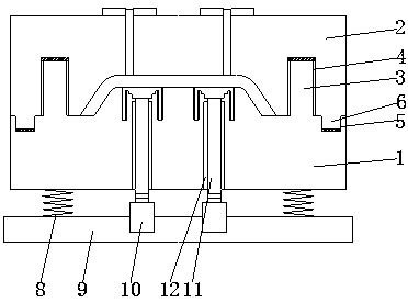
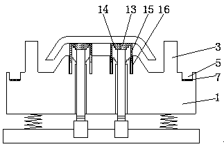
[0016] see Figure 1~2 , in an embodiment of the present invention, an ejection mechanism for mold demoulding of an automobile plastic front fender, comprising a lower mold 1 and an upper mold 2, the top of the lower mold 1 is fixedly provided with a guide post 3, and the guide post 3 is inserted into the first guide In the sleeve 4, the first guide sleeve 4 is embedded in the upper mold 2, and the top of the lower mold 1 on the outer surface of the guide post...


PUM


Abstract

The invention discloses an ejection mechanism for demolding of a plastic head board mold of an automobile. The ejection mechanism comprises a lower mold and an upper mold. Guide columns are fixedly arranged at the top of the lower mold and are inserted into first guide sleeves. The first guide sleeves are embedded in the upper mold. Locating grooves are formed in the positions, on the outer side faces of the guide columns, of the top of the lower mold. Locating blocks cooperating with the locating grooves are also arranged at the bottom of the upper mold. The bottom of the lower mold is fixedly connected with one ends of damper springs, and the other ends of the damper springs are fixedly arranged on a base. Second guide sleeves are embedded in the lower mold. Ejector rods are arranged inthe second guide sleeves. One end of each ejector rod is fixedly connected with a piston rod in an oil cylinder. The oil cylinders are fixedly arranged on the base. An ejector block is fixedly arranged at the other end of each ejector rod. The ejector blocks are connected with the lower mold through connecting portions in an abutting manner. Locating columns are arranged on the side faces of the ejector blocks. The problems that a traditional ejection mechanism is prone to being bent and deforming, and reset is quite difficult are solved.

Description

technical field [0001] The invention relates to the field of automobile plastic moulds, in particular to an ejection mechanism for the demoulding of automobile plastic front baffle moulds. Background technique [0002] In each cycle of injection molding, the plastic part must be taken out of the mold cavity. The mechanism that completes the action of taking out the plastic part is the ejector mechanism, also known as the demoulding mechanism. The plastic front baffle of the car is heavy, the traditional ejector mechanism is easy to bend and deform, and it is difficult to reset, and there is a gap between the ejector mechanism and the mold, and the raw material can easily enter the mold. Contents of the invention [0003] The object of the present invention is to provide a kind of ejector mechanism for mold release of automobile plastic front baffle, so as to solve the problems in the prior art. [0004] In order to achieve the above object, the present invention provides ...

Claims


Application Information

Patent Timeline
Patent Type & Authority Applications(China)
IPC IPC(8): B29C45/26B29C45/40F16F15/06B29L31/30
CPCB29C45/2606B29C45/40B29L2031/3005F16F15/06
Inventor 不公告发明人
Owner 马荣
Learn More