Aircraft empennage structure

A technology of empennage and aircraft, which is applied in the direction of aircraft stability, aircraft parts, aircraft control, etc., can solve the problems of unsatisfactory horizontal heading, etc., and achieve the effect of strong aerodynamic characteristics, novel structure and convenient control

Active Publication Date: 2020-01-17
XIAN AIRCRAFT DESIGN INST OF AVIATION IND OF CHINA
View PDF6 Cites 0 Cited by
  • Summary
  • Abstract
  • Description
  • Claims
  • Application Information

AI Technical Summary

Problems solved by technology

[0003] The tail of a conventional aircraft is composed of a horizontal tail and a vertical tail. The horizontal tail is responsible for the maneuverability and stability of the aircraft in the longitudinal direction, and the vertical tail is responsible for the maneuverability and stability of the horizontal direction. However, for some aircraft with a V-tail layout, the V-tail is simultaneously Responsible for the maneuverability and stability of the aircraft in the longitudinal and lateral directions, it will appear that the longitudinal direction is satisfied, but the lateral direction cannot be satisfied, and vice versa, the lateral direction is satisfied but the longitudinal direction cannot be satisfied

Method used


Image

  • Aircraft empennage structure
  • Aircraft empennage structure
  • Aircraft empennage structure

Examples


Embodiment Construction

[0020] In order to make the purpose, technical solution and advantages of the application more clear, the technical solution in the embodiment of the application will be described in more detail below in conjunction with the drawings in the embodiment of the application. In the drawings, the same or similar reference numerals denote the same or similar elements or elements having the same or similar functions throughout. The described embodiments are some, but not all, embodiments of the application. The embodiments described below by referring to the figures are exemplary, and are intended to explain the present application, and should not be construed as limiting the present application. Based on the embodiments in this application, all other embodiments obtained by persons of ordinary skill in the art without creative efforts fall within the protection scope of this application. Embodiments of the present application will be described in detail below in conjunction with th...


PUM


Abstract

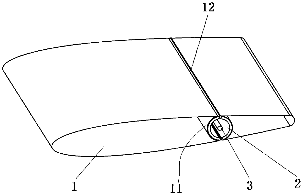
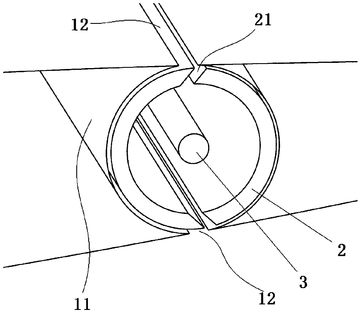
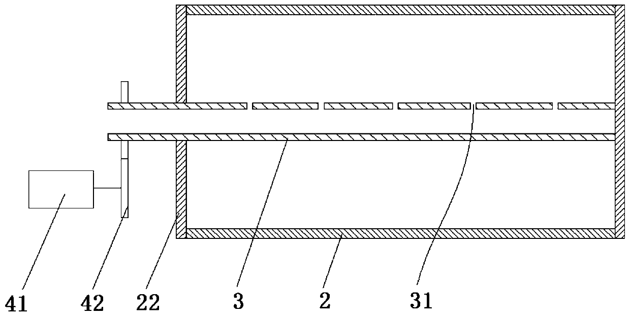
The invention belongs to the field of aircraft structure design, and particularly relates to an aircraft empennage structure which comprises an empennage body, a jet rotor, a hollow jet flow rotatingshaft and a driving mechanism. A cylindrical inner cavity is formed in the empennage body, first jet flow openings are symmetrically formed in two side faces of the empennage body, and two side facesof the empennage body communicate with cylindrical inner cavity. The rotating shaft is coaxially and rotationally arranged in the cylindrical inner cavity; a second jet flow opening is formed in the outer wall of the jet flow rotor, in the rotating process of the jet flow rotor, at a certain moment, the two first jet flow openings can be sealed and blocked by the outer wall of the jet flow rotor,and at the same moment, the second jet flow opening can only coincide with and be in butt joint with one first jet flow opening, and the other first jet flow opening is sealed and blocked; one end opening of the hollow jet flow rotating shaft is connected with an air source and penetrates into the jet flow rotor, and a plurality of air outlet holes are formed in the outer wall; and the driving mechanism is used for driving the jet rotor to rotate. The aircraft empennage structure is novel in structure and convenient to control, and the aerodynamic characteristics of the whole empennage structure are higher.

Description

technical field [0001] The application belongs to the field of aircraft structure design, in particular to an aircraft empennage structure. Background technique [0002] An empennage is a device mounted on the tail of an aircraft that steers and stabilizes the aircraft. The tail can be used to control the pitch, yaw and tilt of the aircraft to change its flight attitude, and it is an important part of the flight control system. [0003] The tail of a conventional aircraft is composed of a horizontal tail and a vertical tail. The horizontal tail is responsible for the maneuverability and stability of the aircraft in the longitudinal direction, and the vertical tail is responsible for the maneuverability and stability of the horizontal direction. However, for some aircraft with a V-tail layout, the V-tail is simultaneously Responsible for the maneuverability and stability of the aircraft in the longitudinal and lateral directions, it will appear that the longitudinal directio...

Claims


Application Information

Patent Timeline
Patent Type & Authority Applications(China)
IPC IPC(8): B64C5/00
CPCB64C5/00
Inventor 吉桂兴
Owner XIAN AIRCRAFT DESIGN INST OF AVIATION IND OF CHINA
Why Eureka
Try Eureka