
Self-film-cutting type aluminum profile double-side-face synchronous film pasting machine

An aluminum profile and film laminating machine technology, which is applied in the direction of winding strips, packaging, thin material processing, etc., can solve the problems of low lamination fastness, low lamination efficiency, insufficient contact, etc., to reduce lamination stations, improve The effect of film sticking efficiency and cost reduction

Inactive Publication Date: 2020-01-17
奋安铝业股份有限公司
View PDF5 Cites 4 Cited by
  • Summary
  • Abstract
  • Description
  • Claims
  • Application Information

AI Technical Summary

Problems solved by technology

[0004] This technical solution has the following deficiencies: one, the film sticking station implemented in this technical mode is located above the aluminum profile, and the single delivery of the aluminum profile can only satisfy the need to carry out filming on the top surface of the aluminum profile. If the film is applied on both sides of the symmetry, the aluminum profile needs to be turned over and transported again; in this way, the efficiency of the film is low; secondly, after the film is applied, multiple aluminum profiles after the film need to be bundled and packaged; The blanking before bundling is mostly manual blanking. If this technical solution is used for subsequent blanking, it will lead to poor process continuity and low work efficiency; If the surface is directly attached to the film, the adhesion fastness will be low; and the device lacks a mechanism for pre-cleaning the surface of the aluminum profile to be filmed before the film is applied. Direct filming will cause Technical problem of poor film effect
However, the cleaning mechanism of this technical solution has the following deficiencies: first, the cleaning roller is set at a height of the film sticking device through the lifting device, which is inconvenient to install; second, the cleaning roller is passively rotated by force, and there may be insufficient contact to cause rotation. Insufficient failure; if the rotation fails, the full utilization of the cleaning roller peripheral surface cannot be achieved
[0007] In addition, the film laminating machines of the prior art mostly use manual cutting of the film after laminating the profile, which is not convenient for the automatic promotion of industrial equipment.

Method used


Image

  • Self-film-cutting type aluminum profile double-side-face synchronous film pasting machine
  • Self-film-cutting type aluminum profile double-side-face synchronous film pasting machine
  • Self-film-cutting type aluminum profile double-side-face synchronous film pasting machine

Examples


Embodiment 1

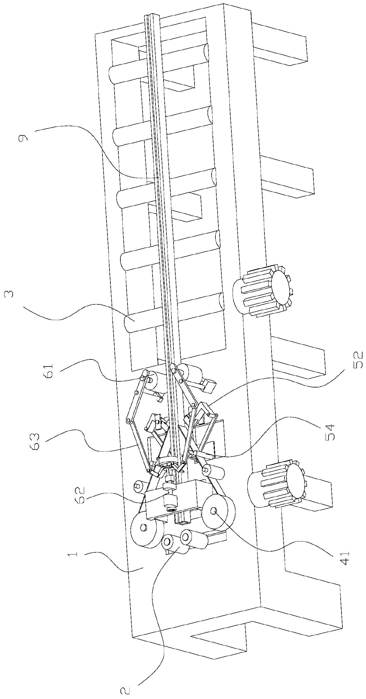
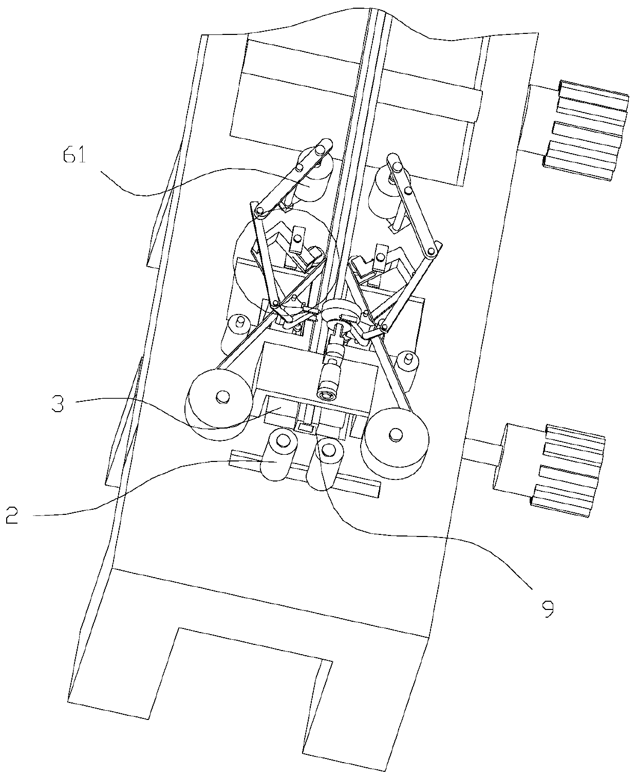
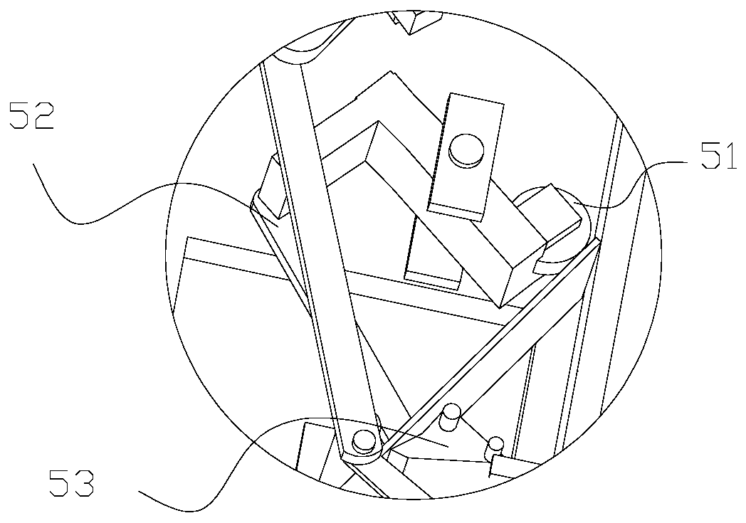
[0057] Such as Figure 1-3 As shown, this embodiment discloses a self-cutting film-type aluminum profile double-sided synchronous film laminating machine, including a frame 1, a pair of limit rollers 2, a guide roller 3, a roll film roller 41, a contact roller 51, a transmission mechanism 52, a cutting Knife 53, guide film roller 54, pressure film roller 61, telescoping rod 62, clamping mechanism 63, elastic device. The limit pair of rollers 2 is located at the front end of the frame 1, and is used to limit the position of the aluminum profile 9 input to the film laminating machine. The guide rollers 3 are rotatably connected with the frame 1, and several guide rollers 3 are distributed from the front end of the frame 1 to the rear end of the frame 1 at intervals. In this embodiment, one or several guide rollers 3 at the front are used as driving rollers, driven by a motor to rotate, and other guide rollers 3 are used as driven rollers. Certainly, the present invention is no...

Embodiment 2

[0072] Such as Image 6 As shown, the difference between this embodiment and the above-mentioned embodiment is that an installation groove 12 is provided on the top of the front end of the frame 1, the bottom of the guide film roller 54 is fixed on the installation groove 12, and the cutting knife mounting part 523 is connected with the installation groove 12. They are rotatably connected by the first connecting shaft. Both ends of the transmission member 522 are respectively hinged to the bottom of the cutting knife mounting part 523 and the bottom of the contact roller mounting part 521 .

[0073] When actually carrying out the side film sticking, since the distance between the bottom of the film and the top surface of the frame 1 is small, in order to ensure that the transmission mechanism 52 has enough installation space and the needs of low-level installation, the present invention places the top of the front end of the frame 1 The installation groove 12 is opened, and t...

Embodiment 3

[0075] Such as Figure 10 , 11 As shown, the difference between the present embodiment and the above-mentioned embodiments is that: a first guide groove 13 is provided on the top of the front end of the frame 1, and the guiding direction of the first guide groove 13 is perpendicular to the direction in which the aluminum profile 9 is conveyed. The bottom of the contact roller mounting part 521 is slidingly matched with the first guide groove 13 . The inner bottom of the mounting groove 12 defines a second guiding groove 121 , and the guiding direction of the second guiding groove 121 is consistent with the guiding direction of the first guiding groove 13 . A sliding block 122 is slidably fitted on the second guide groove 121 , the bottom of the film guiding roller 54 is fixed on the sliding block 122 , and the cutting knife mounting part 523 is rotationally connected with the sliding block 122 through a first connecting shaft.

[0076] Since the contact roller 51 of the pres...


PUM


Abstract

The invention discloses a self-film-cutting type aluminum profile double-side-face synchronous film pasting machine. A contact roller and a cutting knife are in linkage through a transmission mechanism, wherein the contact roller is located behind a film rolling roller, and a part of the contact roller coincides with the conveying track of an aluminum profile; a knife edge of the cutting knife makes contact with a film guiding roller; when the contact roller rotates to the outer surface of the contact roller through the transmission mechanism to make rolling contact with the outer surface of the area, subjected to film pasting, in the aluminum profile, the cutting knife can rotate, a gap exists between the knife edge of the cutting knife and the film guiding roller, and an elastic device deforms; a film unwound from the film rolling roller can pass through the gap; and two sets of film pressing rollers are symmetrically arranged at the two ends of a clamping mechanism, telescopic rodsdo telescopic motion to be used for adjusting the distance between the two ends of the clamping mechanism, and the two sets of film pressing rollers make rolling contact with the corresponding side faces of the area, subjected to film pasting, in the aluminum profile correspondingly. The self-film-cutting type aluminum profile double-side-face synchronous film pasting machine has the advantages that synchronous film pasting of the two opposite side faces of the aluminum profile is achieved, the mechanical structure for automatically cutting off the film is optimized, and operation convenienceis improved.

Description

technical field [0001] The invention relates to the technical field of aluminum profile processing, in particular to a self-cut film-type aluminum profile double-sided synchronous film laminating machine. Background technique [0002] After the aluminum profile is extruded, cut and formed, it needs to be treated with film. The purpose of the film is to provide a certain protection for the surface of the aluminum profile, to prevent it from being scratched and scratched by external force during transportation and handling. [0003] At present, the aluminum profile film is mostly carried out on the film laminating machine. The film sticking machine of the prior art is a kind of film sticking device for aluminum profiles disclosed in patent application 2017215635247. The film sticking method for aluminum profiles disclosed in this technical solution is a film sticking way commonly used in factories at present. Specifically, by placing the aluminum profile on the film laminati...

Claims


Application Information

Patent Timeline
IPC IPC(8): B65B33/02B65B61/06B65H23/188
CPCB65B33/02B65B61/06B65H23/1888B65H2701/1133B65H2701/1752B65H2801/81
Inventor 王芋王若来
Owner 奋安铝业股份有限公司
Learn More