Base assembly of dye vat system

A dye vat and component technology, applied in the field of machinery, can solve the problems of the uncompact structure of the dye vat system, the cumbersome positioning and connection of the dye vat, etc., and achieve the effects of improving the connection stability, compact structure and improving stability.

Inactive Publication Date: 2020-01-17
海宁市创兴经编有限公司
View PDF7 Cites 0 Cited by
  • Summary
  • Abstract
  • Description
  • Claims
  • Application Information

AI Technical Summary

Problems solved by technology

However, each dye vat is connected separately on the ground, which makes the positioning and connection of the dye vat cumbersome, and the structure of the entire dye vat system is not compact

Method used


Image

  • Base assembly of dye vat system
  • Base assembly of dye vat system
  • Base assembly of dye vat system

Examples


Embodiment Construction

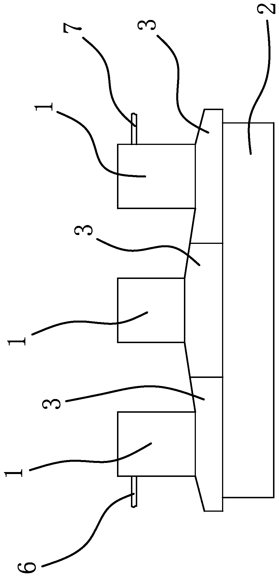
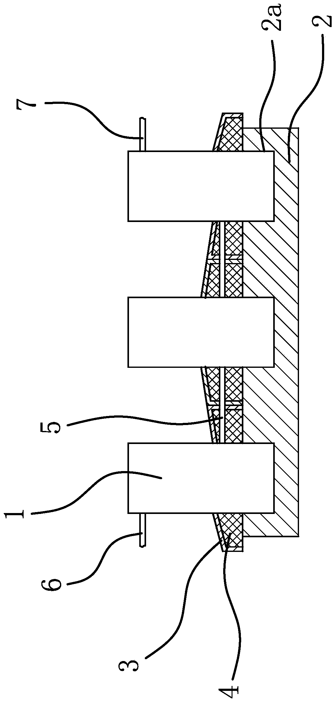
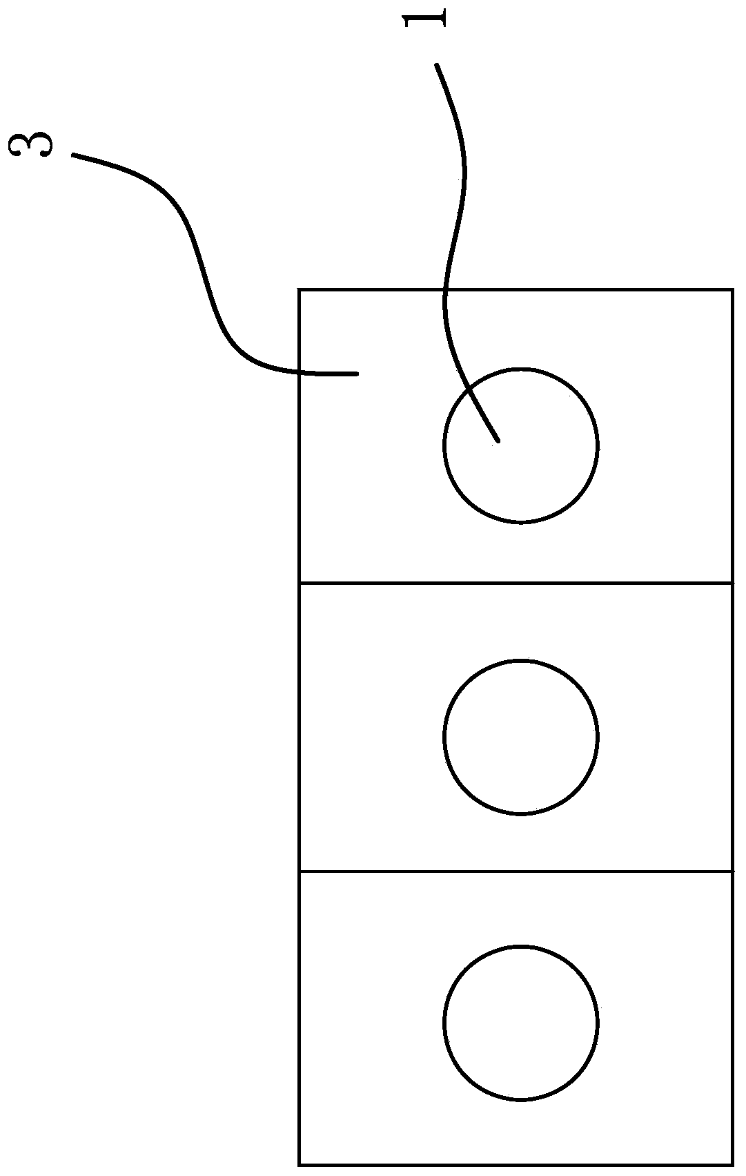
[0023] Such as figure 1 with figure 2 with image 3 As shown, the interior of the dyeing vat is a cavity, and there are several dyeing vats connected in series in sequence.

[0024] The base assembly of the dye vat system includes a base plate 2 and a positioning cover 3. The base plate 2 is in the shape of a long plate. The upper surface of the base plate 2 has a number of concave positioning notches 2a along its length direction. Matching and the lower end of the dyeing vat 1 is connected to the positioning notch 2a, the number of the dyeing vat 1 is the same as the number of the positioning notch 2a, and the two are arranged in one-to-one correspondence. The above-mentioned positioning cover 3 has a through connection hole, and the above-mentioned positioning cover 3 is in one-to-one correspondence The sleeve is placed on the dye vat 1 and the lower end of the positioning cover 3 abuts against the base plate 2, and the side parts of two adjacent positioning covers 3 main...


PUM


Abstract

The invention provides a base assembly of a dye vat system, and belongs to the technical field of machinery. The problem of poor stability in the prior art is solved. The base assembly of the dye vatsystem comprises a base plate and positioning covers. The bottom plate is in the shape of a long plate, and the upper surface of the bottom plate is provided with a plurality of recessed positioning notches in the length direction of the bottom plate; the lower ends of dye vats are matched with the positioning notches, and the lower ends of the dye vats are connected to the positioning notches. The number of the dye vats and the number of the positioning notches are the same, and the dye vats and the positioning notches are in one-to-one correspondence; each positioning cover is provided witha through connecting hole, the positioning covers are arranged on the dye vats in a one-to-one correspondence mode, the lower ends of the positioning covers are abutted to the bottom plate, and the sides of every two adjacent positioning covers are in surface contact. The base assembly of the dye vat system is high in stability.

Description

technical field [0001] The invention belongs to the technical field of machinery and relates to a base assembly of a dye vat system. Background technique [0002] Dyeing vats are used to dye fabrics, and existing dyeing vats are usually of a single structure. There are usually multiple dyeing vats in the process of industrial production, and it is necessary to remove the dye solution for each dyeing vat when cleaning the dyeing vats. [0003] It can be seen that the specific operation process is time-consuming and energy-intensive and the operation efficiency is not high. [0004] In order to solve the above problems, people connect several adjacent dye vats in series as an overall system. However, each dyeing vat is connected separately on the ground, which makes the positioning and connection of the dyeing vats complicated, and the structure of the entire dyeing vat system is not compact. Contents of the invention [0005] The object of the present invention is to pro...

Claims


Application Information

Patent Timeline
Patent Type & Authority Applications(China)
IPC IPC(8): D06B23/00D06B23/20
CPCD06B23/00D06B23/20
Inventor 蒋建荣苏荣尚蒋颖晓
Owner 海宁市创兴经编有限公司
Why Eureka
Try Eureka