
Assembled installation trolley for laminated slabs, and use method thereof

A laminated board and prefabricated technology, applied in construction, building structure, construction material processing and other directions, can solve the problems of low installation efficiency, occupation of tower cranes, low work efficiency, etc., to achieve overall structural stability, reduce occupation time, improve The effect of installation efficiency

Active Publication Date: 2020-01-17
CSCEC STRAIT CONSTR & DEV
View PDF9 Cites 1 Cited by
  • Summary
  • Abstract
  • Description
  • Claims
  • Application Information

AI Technical Summary

Problems solved by technology

[0003] Since the two ends of the laminated slab are framed on the beam or wall, and the contact surface at both ends is only 1cm wide, the installation of the laminated slab with a tower crane cannot meet the accuracy requirements of the installation position, and the manual assisted method is used, and the installation process requires workers to constantly adjust The horizontal position of the laminated slab, the overall work efficiency is low, and it takes a long time to occupy the tower crane to assist the installation of the laminated slab, which cannot meet the requirements of rapid construction
[0004] After searching, the publication number is CN109723237A, which is an invention patent application titled "Portable Support System and Construction Method Based on Prefabricated Floor Slab". The support system can support the prefabricated floor. The structure of the height adjustment rod of the support is used to realize the lifting of the laminated board, the structure is not stable enough, and the adjustment rods on both sides are difficult to ensure the synchronization of adjustment; in addition, the movement of the support system is inconvenient, and the position of the support system can only be manually moved and The position of the laminated slab on the support system is manually moved, and the installation efficiency is low. It is not suitable for the installation of the laminated slab that requires extremely high progress in the installation position, and the height that can be lifted is limited. If a higher height is required, the site occupied just big
[0005] In addition, there is an invention patent application with the publication number CN110080537A titled "A Prefabricated Laminated Panel Positioning, Hoisting and Supporting Method". The vertical rod supporting the laminated slab under the laminated slab can only move along one direction and the other direction perpendicular to this direction when adjusting the laminated slab, and cannot realize the adjustment of the turning position, which cannot satisfy the current fast construction of the corresponding laminated slab. construction requirements

Method used


Image

  • Assembled installation trolley for laminated slabs, and use method thereof
  • Assembled installation trolley for laminated slabs, and use method thereof
  • Assembled installation trolley for laminated slabs, and use method thereof

Examples


Embodiment 1

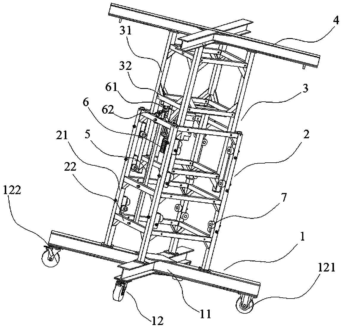
[0042] see Figure 1 to Figure 7 , an assembled laminated board installation trolley, including a movable base 1, a first stand 2 fixed on the base 1, sleeved in the first stand 2 and can move up and down relative to the first stand 2 The second stand 3 and the top support 4 fixed on the top surface of the second stand 3 .

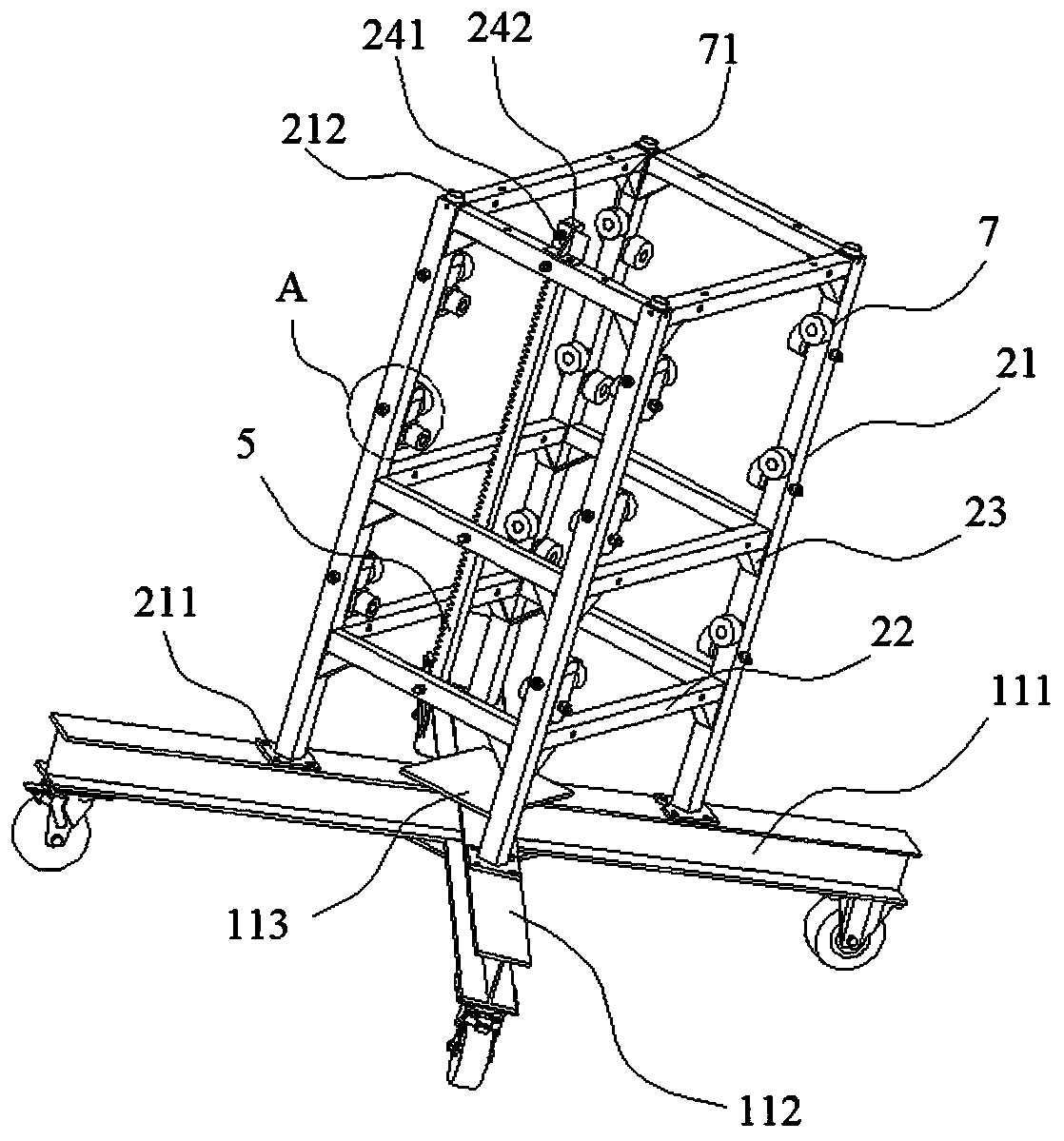
[0043]The base 1 includes a base body 11 and moving wheels 12 connected under the base body 11 . As an embodiment of the seat body 11, the seat body 11 can be welded into a cross shape by using I-beams. In this embodiment, the seat body 11 includes a long steel 111 and short steel 112 arranged perpendicular to the long steel 111 and welded on both sides of the middle of the long steel 111, the long steel 111 and the two short steel 112 are connected to form a cross And the top surface and the bottom surface are respectively flush. Preferably, a connecting plate 113 connecting the long steel 111 and the short steel 112 is welded on the top surface and th...

Embodiment 2

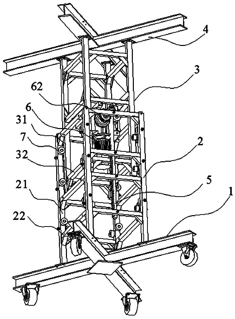
[0060] see Figure 8 to Figure 12 , a prefabricated laminated plate installation trolley, including a movable base 1, a first stand 2 fixed on the base 1, sleeved outside the first stand 2 and movable up and down relative to the first stand 2 The second stand 3 and the top support 4 fixed on the top surface of the second stand 3 .

[0061] The structure of the base 1 is the same as that of the base 1 in the first embodiment, and will not be repeated here.

[0062] The first stand 2 is connected by a plurality of vertically arranged first columns 21 and a plurality of horizontally or obliquely arranged first cross bars 22 to form a frame structure. The top surface of the first column 21 is provided with an upwardly convex locking protrusion 212 . A main rack 5 is vertically fixed outside the plurality of first cross bars 22 on the same side of the first stand 2 . A non-toothed limiting block 242 is detachably connected to the top of the main body rack 5 .

[0063] The secon...


PUM


Abstract

The invention relates to an assembled installation trolley for laminated slabs, and a use method thereof. The trolley comprises a movable base, a first vertical frame fixed to the base, a second vertical frame arranged in or outside the first vertical frame in a sleeved manner and capable of moving up and down relative to the first vertical frame, and a top support fixed to the top surface of thesecond vertical frame, wherein a moving wheel is arranged on the bottom surface of the base, a vertically-arranged main body rack is fixed to the first vertical frame, a lifting motor with a speed reducer is fixed to the second vertical frame, a gear is fixedly arranged on an end part of an output shaft of the speed reducer in a sleeved manner, and the gear is engaged with the main body rack; andan extension frame capable of increasing the height of the first vertical frame is detachably connected to the first vertical frame, a vertically-arranged extension rack is fixed to the side which isthe same as the side provided with the main body rack, of the first vertical frame, of the extension frame, and when the extension frame is placed on the first vertical frame, the bottom surface of the extension rack clings to the top surface of the main body rack of the first vertical frame. The trolley is capable of realizing accurate and rapid installation for the laminated slabs, so that the occupied time of a tower crane is reduced.

Description

technical field [0001] The invention relates to the technical field of auxiliary equipment for construction of laminated slabs, in particular to an assembled trolley for installing laminated slabs and a method for using the same. Background technique [0002] Traditional laminated panels are hoisted by tower cranes and require manual installation with manual assistance. The installation process of the traditional laminated slab is as follows: the tower crane lifts the laminated slab to a certain position, then several workers need to manually intervene to move the laminated slab to the required position, and finally the tower crane slowly descends until the laminated slab is in place. [0003] Since the two ends of the laminated slab are framed on the beam or wall, and the contact surface at both ends is only 1cm wide, the installation of the laminated slab with a tower crane cannot meet the accuracy requirements of the installation position, and the manual assisted method i...

Claims


Application Information

Patent Timeline
IPC IPC(8): E04G21/16
CPCE04G21/167
Inventor 王耀徐洪广何友泉魏炜郑辉
Owner CSCEC STRAIT CONSTR & DEV
Features
  • Generate Ideas
  • Intellectual Property
  • Life Sciences
  • Materials
  • Tech Scout
  • Unparalleled Data Quality
  • Higher Quality Content
  • 60% Fewer Hallucinations
Learn More