Worktable base used for manufacturing of energy-saving lamps

A technology of work and pedestal, applied in cleaning methods and utensils, cleaning hollow objects, material gluing, etc., can solve problems such as low efficiency and poor precision, and achieve the effects of improving quality, reducing lamp damage, and inhibiting displacement

Active Publication Date: 2020-01-17
湖南德霸照明制造有限公司
View PDF11 Cites 0 Cited by
  • Summary
  • Abstract
  • Description
  • Claims
  • Application Information

AI Technical Summary

Problems solved by technology

[0004] Aiming at the deficiencies of the prior art, the present invention provides a workbench for the manufacture of energy-saving lamps, mainly to solve the problems of a large number of human-operated steps, poor precision and low efficiency in the production process of lamps

Method used


Image

  • Worktable base used for manufacturing of energy-saving lamps
  • Worktable base used for manufacturing of energy-saving lamps
  • Worktable base used for manufacturing of energy-saving lamps

Examples


Embodiment 1

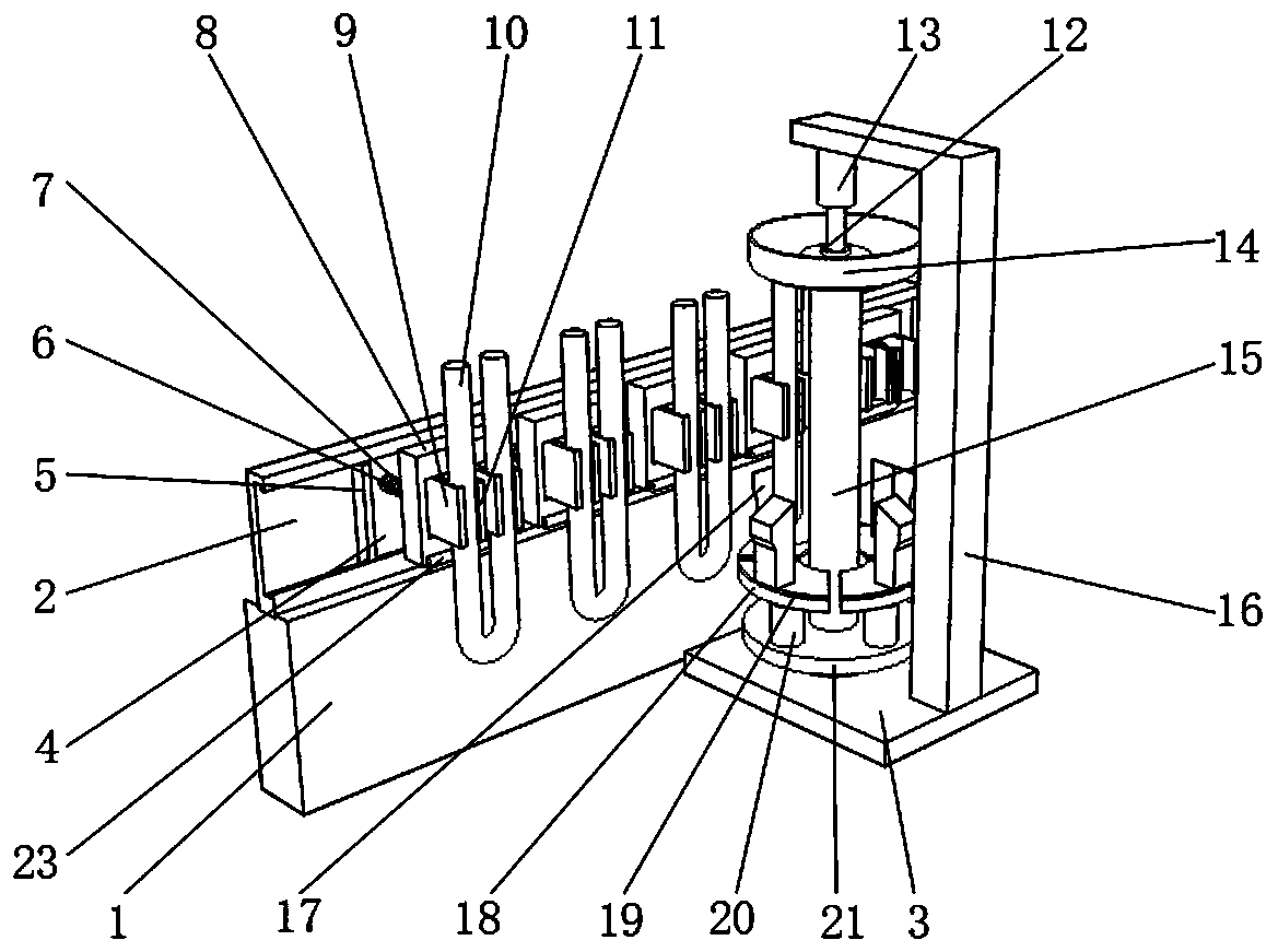
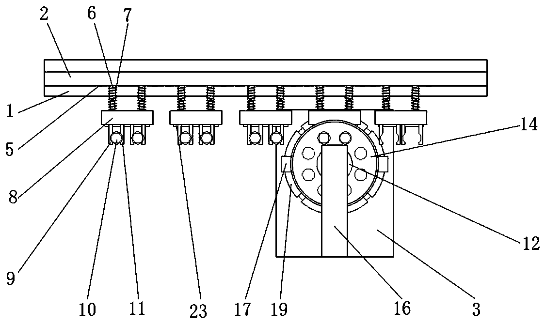
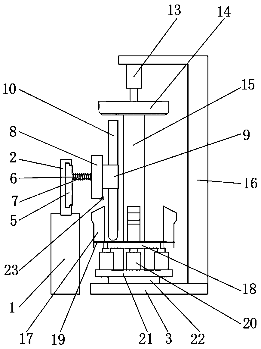
[0022] refer to Figure 1-4 , a workbench for the manufacture of energy-saving lamps, including a fixed seat 1 and a base 3, the top of the fixed seat 1 is slidably connected to a conveying frame 2, and a groove is opened on one side of the conveying frame 2, and a fixing plate 4 and a fixed plate 4 are slidably connected in the groove Limiting plate 5, the height of fixed plate 4 is consistent with the height of groove, and one side of fixed plate 4 is welded with movable rod 6, and movable rod 6 is sleeved with spring 7, and one end of movable rod 6 is welded with mounting plate 8, and The stroke of the movable rod 6 is greater than the distance between the fixed plate 4 and the fixed seat 1, the fixed plate 4 moves in the groove of the conveyor frame, and the lamp conveyor belt is assigned a position, and the top of the base 3 is welded with a rotating shaft 22 and a mounting frame 16, and One side of the installation frame 16 is welded with a telescopic rod 13, the bottom ...

Embodiment 2

[0025] Embodiment 2 refers to Figure 5-6, a workbench for the manufacture of energy-saving lamps, which also includes a control box 25, the control box 25 is welded on the top of the installation frame 16, and an air pump 26 is connected to one side of the control box 25 through bolts, and the air pump 26 generates air for the air blowing pipe 27, and recovers The air inhaled by the suction pipe 28 is welded with two casings at the bottom of the control box 25, and the two casings are respectively sleeved with a blowing pipe 27 and a suction pipe 28, and the blowing pipe 27 and the suction pipe 28 go deep into the top of the lamp tube 10 respectively. opening.

[0026] Working principle of this embodiment: when in use, the support plate 18 lifts the lamp tube 10 through the lifter 20, and when the lamp tube 10 passes through the hole of the lamp holder 14, the control box 25 controls the blowing pipe 27 and the suction pipe 28 to extend. into the lamp tube 10, the air pump 2...


PUM


Abstract

The invention relates to the technical field of lamp manufacturing, and discloses a worktable base used for manufacturing of energy-saving lamps. The worktable base comprises a fixed base and a bottombase; the top of the fixed base is slidably connected to a conveying rack; a groove is formed in one side of the conveying rack and is slidably connected to a fixed plate and a limiting plate; the height of the fixed plate is the same as that of the groove; besides, a movable rod is welded to one side of the fixed plate; a spring sleeves the movable rod; an assembly plate is welded to one end ofthe movable rod; besides, the stroke of the movable rod is larger than the distance between the fixed plate and the fixed base; and a rotary shaft and an assembly rack are welded to the top of the bottom base. According to the worktable base, through cooperation of connection blocks and rollers, the assembly plate and fixing clamp groups arranged on the assembly plate move backwards while lamp tubes are lifted by the supporting plate; multiple steps are finished through one action; production equipment is simplified; production cost is lowered while production efficiency is obviously improved;and the resource utilization rate is improved.

Description

technical field [0001] The invention relates to the technical field of lamp manufacturing, in particular to a working bench for energy-saving lamp manufacturing. Background technique [0002] As we all know, the energy-saving lamp manufacturing workbench is a kind of manufacturing equipment for bonding the lamp tube of the energy-saving lamp on the lamp holder, and it has been widely used in the field of the industry; Glass lamp tube assembly workbench, special-shaped glass lamp tube assembly workbench; the existing energy-saving lamp manufacturing workbench is found to be low in automation, poor in operation accuracy, and requires a lot of manual operations. [0003] After searching, the authorized publication number is CN105834732B patent, which discloses a lamp assembly machine, which is used to assemble the connector to the lamp housing, and align the wires in the lamp housing to the perforation of the connector. The lamp assembly machine includes a base, Assembling dev...

Claims


Application Information

Patent Timeline
Patent Type & Authority Applications(China)
IPC IPC(8): F16B11/00B08B9/032
CPCB08B9/0321F16B11/006
Inventor 陆卫黄陆文辉张冬
Owner 湖南德霸照明制造有限公司
Why Eureka
Try Eureka