An electronically controlled electric rotor brake system

A brake system and rotor technology, applied in the direction of brake type, brake actuator, axial brake, etc., can solve the problems of multiple acquisition signals, complex structure design, high operating cost, etc., achieve short disassembly time, convenient installation and maintenance, The effect of improving system reliability

Active Publication Date: 2021-03-26
哈尔滨哈飞航空工业有限责任公司
View PDF10 Cites 0 Cited by
  • Summary
  • Abstract
  • Description
  • Claims
  • Application Information

AI Technical Summary

Problems solved by technology

The system collects many signals, the structure design is complicated, and the operation cost is high

Method used


Image

  • An electronically controlled electric rotor brake system
  • An electronically controlled electric rotor brake system
  • An electronically controlled electric rotor brake system

Examples


Embodiment Construction

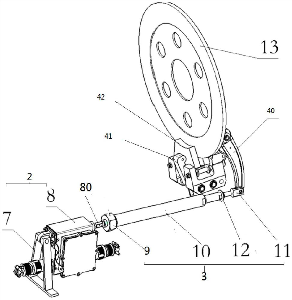
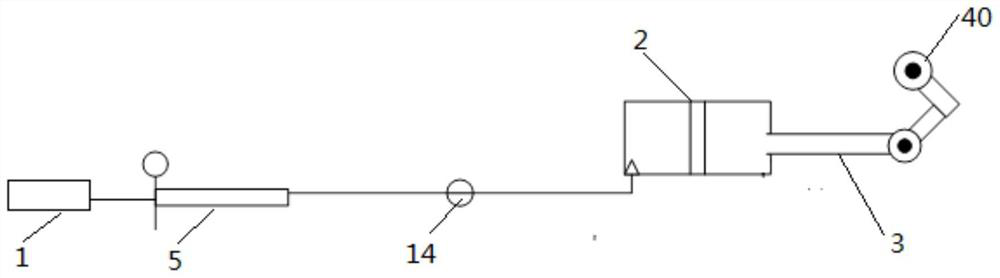
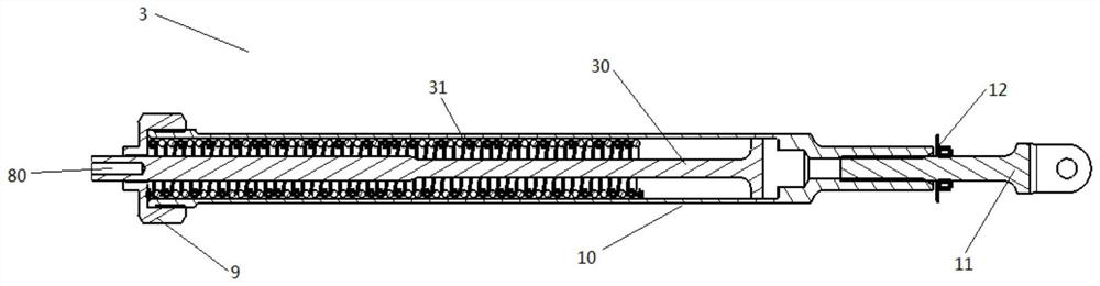
[0034] figure 1 It is an axonometric view of the electric mechanism assembly, connection assembly and rotor brake stop mechanism connection mode in the electronically controlled electric rotor brake system of this embodiment, figure 2 It is a schematic diagram of the working principle of the electronically controlled electric rotor brake system of this embodiment, combined with figure 1 and figure 2 As shown, this embodiment provides an electronically controlled electric rotor brake system for helicopter rotor brakes. The brake system includes a control system 1, an electric mechanism assembly 2, a connection assembly 3, and a rotor brake stop mechanism. The motor mechanism assembly 2 includes a driving mechanism 8 , and the connecting assembly 3 includes a connecting pipe 10 .

[0035] like figure 2 As shown, the control system 1 is electrically connected with the driving mechanism 8 for controlling the movement of the driving mechanism 8 . like figure 1 As shown, the...


PUM


Abstract

The invention provides an electronically-controlled electric rotor wing brake system which is used for a rotor wing brake of a helicopter. The brake system includes a control system 1, an electric mechanism component 2, a connection component 3 and a rotor wing brake stop mechanism. The electric mechanism component 2 includes a driving mechanism 8; the control system 1 is electrically connected with the driving mechanism 8 and is used for controlling the driving mechanism 8 to move; an output shaft 80 of the driving mechanism 8 is in threaded connection with one end of the connection component3, the output shaft 80 of the driving mechanism 8 rotates to drive the connection component 3 to move in the axis direction; and the other end of connection component 3 is fixedly connected to the rotor wing brake stop mechanism, the connection component 3 moves in the axis direction, the rotor wing brake stop mechanism is driven to move, and the rotor wing brake stop mechanism stops a rotor wing.

Description

technical field [0001] The invention belongs to the technical field of helicopter transmission design and relates to an electronically controlled electric rotor braking system. Background technique [0002] The function of the helicopter rotor brake system is that when the helicopter is on the ground, when the engine is stopped, the rotor brake is used within the specified rotor speed. It can shorten the rotor stop time, quickly brake the blades, and park the helicopter on the ground. Keep the rotor blades stationary. At present, most of them adopt two structures of mechanically controlled mechanical brakes and mechanically controlled hydraulic brakes. [0003] Mechanical control The mechanical brake structure generally adopts the combination of cockpit rotor brake mechanical control handle, linkage reversing structure, rotor brake control cable, elastic actuation mechanism, and mechanical rotor brake device. Through the operation of the driver, the brake is driven. The br...

Claims


Application Information

Patent Timeline
Patent Type & Authority Patents(China)
IPC IPC(8): F16D55/226F16D65/18F16D121/24
CPCF16D55/226F16D65/18F16D2121/24
Inventor 徐书博柴郁琳赵沛然张贺高佳鑫李明王锐
Owner 哈尔滨哈飞航空工业有限责任公司
Why Eureka
Try Eureka