
A hydraulic pipeline connector

A technology for hydraulic pipelines and pipe joints, applied in the direction of pipes/pipe joints/fittings, adjustable connections, pipeline protection, etc. It can solve problems such as leakage, affect work progress, increase costs, etc., and achieve the effect of convenient use and accelerated work efficiency

Active Publication Date: 2021-06-15
宁波联润流体机械制造有限公司
View PDF5 Cites 0 Cited by
  • Summary
  • Abstract
  • Description
  • Claims
  • Application Information

AI Technical Summary

Problems solved by technology

[0003] In the pipeline system of the machine, the pipeline is very important for the operation of the machine, and when the pipeline joint is used for a period of time, some damage will occur, such as: leakage, the pipeline joint needs to be replaced, and the pipeline joint cannot guarantee that the pipeline is in the disassembly process It will not leak. First of all, the main gate of the pipeline needs to be sealed, and then the pipeline joints should be replaced after sealing. It takes a long time to install and replace the pipeline, which reduces work efficiency, increases costs, and also affects work. progress, and the pipe wall at the joint joint is thin, and the joint is relatively fragile due to frequent disassembly and assembly. If the pipe joint breaks, the overall pipeline will lose its function, and the operation of the hydraulic pipeline often requires the pipeline to be turned. , neither the pipeline nor the pipeline joint can make the pipeline turn inconveniently fixed, therefore, a hydraulic pipeline joint is proposed to solve the above problems

Method used


Image

  • A hydraulic pipeline connector
  • A hydraulic pipeline connector
  • A hydraulic pipeline connector

Examples


Embodiment Construction

[0022] In order to make the technical means, creative features, goals and effects achieved by the present invention easy to understand, the present invention will be further described below in conjunction with specific embodiments.

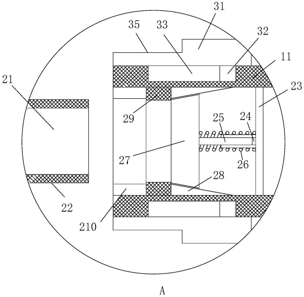
[0023] Such as Figure 1-Figure 5 As shown, a hydraulic pipeline joint according to the present invention includes a pipeline joint 1, a connecting mechanism 2, a protection mechanism 3, a steering mechanism 4, and a filtering mechanism 5. Both ends of the pipeline joint 1 are provided with a connecting mechanism 2, A protection mechanism 3 is provided on the outside of the connection mechanism 2 , and a steering mechanism 4 and a filter mechanism 5 are arranged inside the pipe joint 1 .

[0024] Specifically, the pipe joint 1 includes a first connecting pipe 11, a second connecting pipe 12, a third connecting pipe 13, a liquid inlet pipe 14, and a liquid outlet pipe 15. One end of the first connecting pipe 11 passes through a connecting mechanism...


PUM


Abstract

The invention relates to the field of pipeline joints, specifically a hydraulic pipeline joint, including a pipeline joint, a connecting mechanism, a protection mechanism, a steering mechanism, and a filtering mechanism. Both ends of the pipeline joint are provided with a connecting mechanism, and the outside of the connecting mechanism is provided with Protection mechanism, the inside of the pipe joint is equipped with a steering mechanism and a filter mechanism. The pipe joint includes a first connecting pipe, a second connecting pipe, a third connecting pipe, a liquid inlet pipe, and a liquid outlet pipe. One end of the first connecting pipe passes through the connecting mechanism The structure is connected with a liquid inlet pipe. By setting up the connecting mechanism, the connecting cylinder in the connecting mechanism is used to push the plug plate to move, and the leakage-proof gasket is set so that the inside of the pipeline will not leak after the connecting cylinder is inserted into the first connecting pipe, so that the pipeline is connected. When the connecting cylinder withdraws When the pipe is first connected, the spring pushes the plug plate to rebound to block the passage, thereby preventing the pipeline from leaking during the connection process, reducing work efficiency, and preventing the work progress from being affected.

Description

technical field [0001] The invention relates to the field of pipeline joints, in particular to a hydraulic pipeline joint. Background technique [0002] In the operation of hydraulic pipelines, it is often encountered that the pipelines are connected. In the process of connecting or disconnecting the pipeline, how to ensure the sealing degree of the pipeline and optimize the connection mode of the connecting joint is a technical problem. [0003] In the pipeline system of the machine, the pipeline is very important for the operation of the machine, and when the pipeline joint is used for a period of time, some damage will occur, such as: leakage, the pipeline joint needs to be replaced, and the pipeline joint cannot guarantee that the pipeline is in the disassembly process It will not leak. First of all, the main gate of the pipeline needs to be sealed, and then the pipeline joints should be replaced after sealing. It takes a long time to install and replace the pipeline, w...

Claims


Application Information

Patent Timeline
Patent Type & Authority Patents(China)
IPC IPC(8): F16L29/02F16L57/00F16L27/107B01D35/02
CPCB01D35/02F16L27/107F16L29/02F16L57/00
Inventor 不公告发明人
Owner 宁波联润流体机械制造有限公司
Learn More