
Transformer Internal Fault Detection and Location Method Based on Acoustic Vibration Coupling Signal

A locating method and technology for internal faults, applied in transformer testing, locating, direction finder using ultrasonic/sonic/infrasonic waves, etc., can solve problems such as large differences in measurement results, complex transformer structure, and aggravating the difficulty of subsequent signal analysis work. , to achieve the effect of accurate positioning and accurate vibration characteristics

Active Publication Date: 2021-08-03
CHONGQING UNIV
View PDF0 Cites 0 Cited by
  • Summary
  • Abstract
  • Description
  • Claims
  • Application Information

AI Technical Summary

Problems solved by technology

However, this method still has some limitations. The measurement results of different measuring points on the transformer oil tank wall are very different, which increases the difficulty of subsequent signal analysis; only collecting vibration signals on the oil tank wall cannot accurately restore the iron core and winding. Due to the complex structure of the transformer, it is impossible to accurately analyze the transmission process of its vibration signal, so it can only preliminarily judge the approximate location of the fault point, and cannot accurately locate the fault point

Method used


Image

  • Transformer Internal Fault Detection and Location Method Based on Acoustic Vibration Coupling Signal
  • Transformer Internal Fault Detection and Location Method Based on Acoustic Vibration Coupling Signal
  • Transformer Internal Fault Detection and Location Method Based on Acoustic Vibration Coupling Signal

Examples


Embodiment Construction

[0042] Embodiments of the present invention are described below through specific examples, and those skilled in the art can easily understand other advantages and effects of the present invention from the content disclosed in this specification. The present invention can also be implemented or applied through other different specific implementation modes, and various modifications or changes can be made to the details in this specification based on different viewpoints and applications without departing from the spirit of the present invention. It should be noted that the diagrams provided in the following embodiments are only schematically illustrating the basic concept of the present invention, and the following embodiments and the features in the embodiments can be combined with each other in the case of no conflict.

[0043] Wherein, the accompanying drawings are for illustrative purposes only, and represent only schematic diagrams, rather than physical drawings, and should...


PUM


Abstract

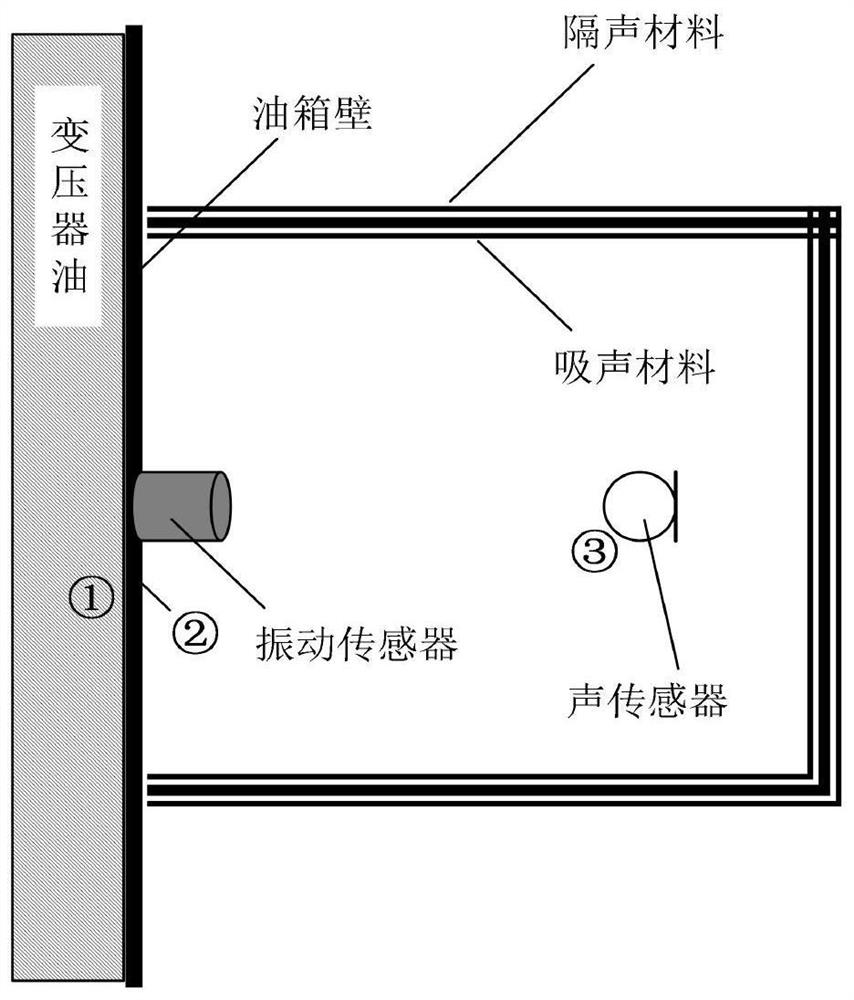
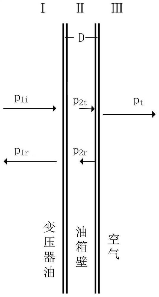
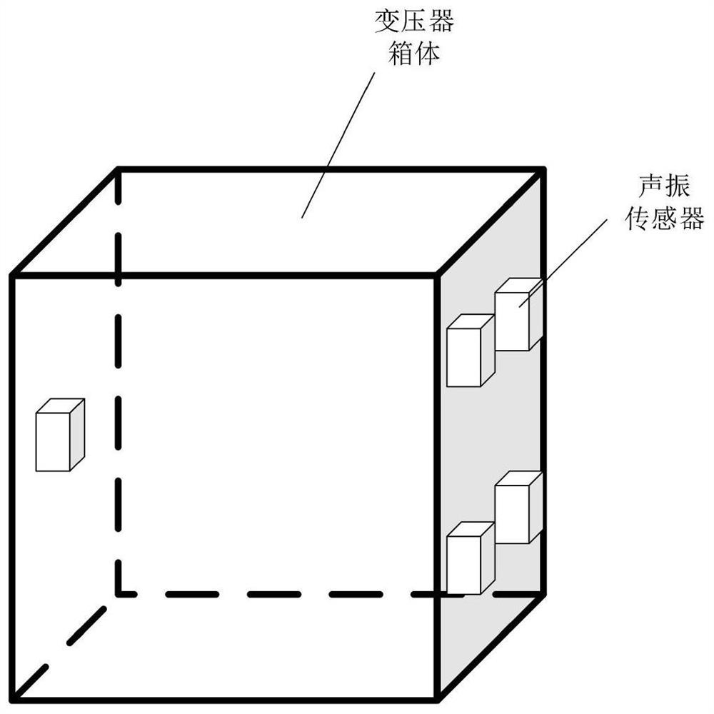
The invention relates to a method for detecting and locating an internal fault of a transformer based on an acoustic-vibration coupling signal, and belongs to the field of transformer monitoring. This method uses the principle of structural vibration acoustic radiation to couple vibration signals and acoustic signals, separates the internal sound field from vibration acoustic radiation, studies the transmission coefficient of sound waves penetrating through the tank wall, and then inverts to obtain the internal acoustic signal of the transformer. The fault diagnosis process adopts joint analysis of vibration signal and acoustic signal to obtain accurate results of fault status, and realizes internal fault location through sensor array. The invention breaks through the limitation of only using a single signal to evaluate the operating state of the transformer, realizes the measurement of the internal sound field of the transformer without power failure and disassembly, and realizes accurate positioning of fault points while improving detection accuracy.

Description

technical field [0001] The invention belongs to the field of transformer monitoring and relates to a method for detecting and locating internal faults of transformers based on acoustic-vibration coupling signals. Background technique [0002] The transformer is a very important link in the power transmission and transformation system, and its normal operation is of great significance to the power supply reliability, stability and security of the power grid. Transformers are usually expensive to manufacture, and they must be repaired with a power outage in case of failure. Not only the maintenance cost is high and the maintenance time is long, but also it will cause a large-scale power outage, resulting in major economic losses. Once a major accident occurs, it will also cause casualties, and the social impact is extremely serious. In order to avoid these accidents, relevant transformer fault detection and condition monitoring technologies must be paid attention to. [0003]...

Claims


Application Information

Patent Timeline
Patent Type & Authority Patents(China)
IPC IPC(8): G01R31/62G01H17/00G01S5/22G01S3/808
CPCG01H17/00G01N29/07G01S3/808G01S5/22
Inventor 张占龙董子健邓军蒋培榆武雍烨肖睿
Owner CHONGQING UNIV
Learn More