
Rotor test bench and test method with spigot connection structure

A technology of connecting structure and testing method, which is applied in the test bench and testing field of the rotor of the spigot connection structure, can solve the problems of large centrifugal force, increase the overall mass of the engine, affect the structural strength of the rotor, etc., and achieve the effect of convenient installation and disassembly.

Active Publication Date: 2019-07-12
NORTHEASTERN UNIV LIAONING
View PDF5 Cites 0 Cited by
  • Summary
  • Abstract
  • Description
  • Claims
  • Application Information

AI Technical Summary

Problems solved by technology

Traditional connection methods such as bolted connections require additional joints, which will increase the overall mass of the engine, and these joints often introduce unbalanced masses, which is extremely critical for rotating machines such as aero engines that work at high speeds. Adverse
In addition, the long tie rods and short bolts in the bolt connection will generate a large centrifugal force when the engine is running at high speed, and holes need to be drilled at the connection position, thus affecting the structural strength of the rotor. These disadvantages limit the performance of the aero-engine to a certain extent promotion

Method used


Image

  • Rotor test bench and test method with spigot connection structure
  • Rotor test bench and test method with spigot connection structure
  • Rotor test bench and test method with spigot connection structure

Examples


Embodiment Construction

[0030] The specific implementation manners of the present invention will be further described below in conjunction with the drawings and technical solutions.

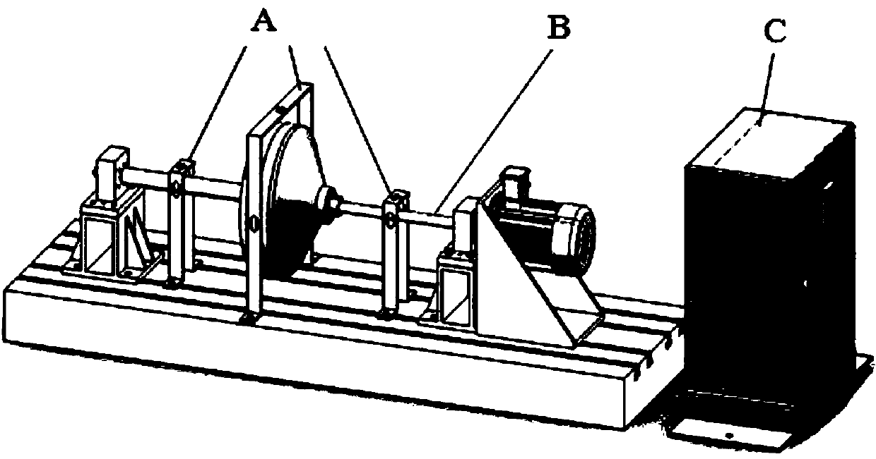
[0031] Such as figure 1 As shown, the present invention is a test device for rotor vibration characteristics considering the spigot connection structure, which mainly includes an electrical control box C, a rotor-support system B and a test sensing system A.

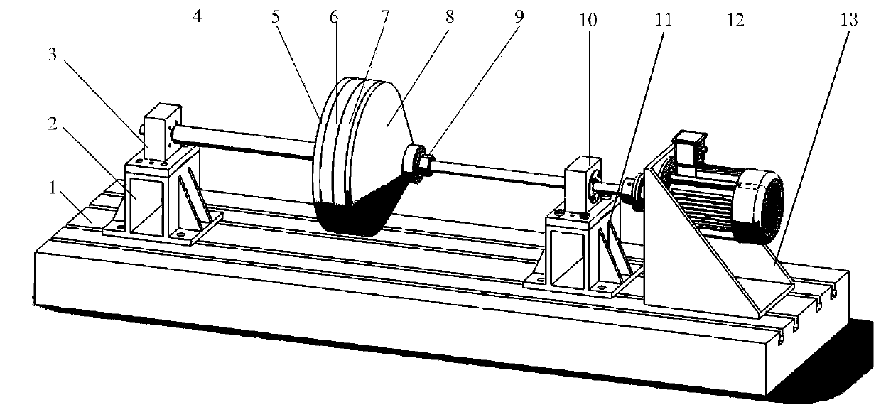
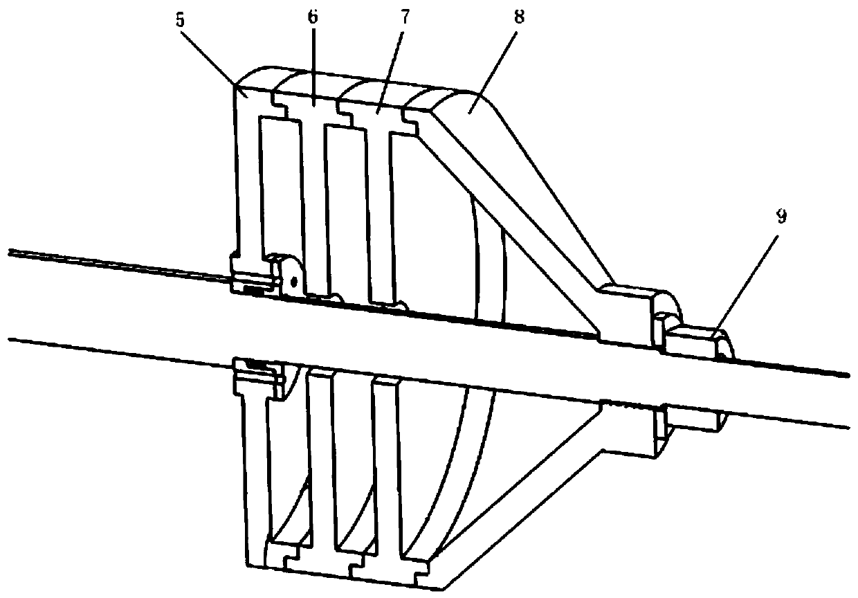
[0032] The rotor-support system B, such as figure 2 with image 3 As shown, it includes base 1, rotating shaft 4, left fixed plate 5, left spigot plate 6, right spigot plate 7, right conical cover 8, lock nut 9, deep groove ball bearing 16, left bearing seat 3, right Bearing seat 10, bearing seat support 2, right bearing seat support 11, variable frequency motor 12 and motor seat 13.

[0033] The base 1 is placed on a level ground, and its upper surface is provided with several T-shaped grooves. The left bearing support 2, the right bearing support 11, the mot...


PUM


Abstract

The invention belongs to the technical field of aeroengine rotor system tests, and relates to a rotor test bench of a spigot connecting structure, and a test method. The test bench is mainly composedof a test sensing system, a rotor-support system and an electrical control box; the test sensing system is mainly composed of vibration test software, a collection card chassis, a collection card, a data collection system, an LMS test device, a modal force hammer and sensor fixing frames; the rotor-support system is mainly composed of a base, a left bearing seat bracket, a left bearing seat, a rotating shaft, a left fixing disc, a left spigot disc, a right spigot disc, a right conical cover, a locking nut, a right bearing seat, a right bearing seat bracket, a variable frequency motor, a motorseat and a deep groove ball bearing; and the electrical control box is connected with the variable frequency motor for adjusting the rotating speed. The rotor test bench provided by the invention is used for studying the influence of the spigot connecting structure and related parameter changes on the inherent characteristics and dynamic characteristics of the rotor system, and providing a test basis for the design of the spigot connecting structures of aeroengines.

Description

technical field [0001] The invention relates to the field of aero-engine rotor system tests, and relates to a test bench and a test method for a rotor with a spigot connection structure. Background technique [0002] An aero-engine is a whole composed of several parts through a connection structure. The existence of a connection structure will reduce the local stiffness of the aero-engine rotor system, thereby changing the vibration characteristics of the rotor system. If the design of the connection structure is unreasonable, it is very likely to cause connection failure during the working process of the aero-engine, which will lead to more serious accidents. At the same time, during the high-speed rotation of the rotor, the connection stiffness will also change with the change of load and working conditions, which makes the dynamic behavior of the rotor system more complicated. Therefore, it has become an important research direction in the field of aero-engine design and...

Claims


Application Information

Patent Timeline
Patent Type & Authority Patents(China)
IPC IPC(8): G01M7/02
CPCG01M7/025
Inventor 杨阳罗忠王菲于清文
Owner NORTHEASTERN UNIV LIAONING
Learn More