Magnetizing inrush current recognition method based on second-order Taylor coefficient

A technology of excitation inrush current and identification method, which is applied in complex mathematical operations, data processing applications, electrical digital data processing, etc., and can solve problems such as weak anti-noise ability

Active Publication Date: 2020-01-17
SOUTHWEST JIAOTONG UNIV
View PDF13 Cites 0 Cited by
  • Summary
  • Abstract
  • Description
  • Claims
  • Application Information

AI Technical Summary

Problems solved by technology

[0004] The purpose of the present invention is: the present invention provides a second-order Taylor coefficient-based excitation inrush identification method, which solves the problem that the existing excitation inrush identification method leads to protection delay action and weak anti-noise ability when a fault occurs, and achieves The effect of accurate and fast discrimination of transformer faults during the blocking period

Method used


Image

  • Magnetizing inrush current recognition method based on second-order Taylor coefficient
  • Magnetizing inrush current recognition method based on second-order Taylor coefficient
  • Magnetizing inrush current recognition method based on second-order Taylor coefficient

Examples


Embodiment 1

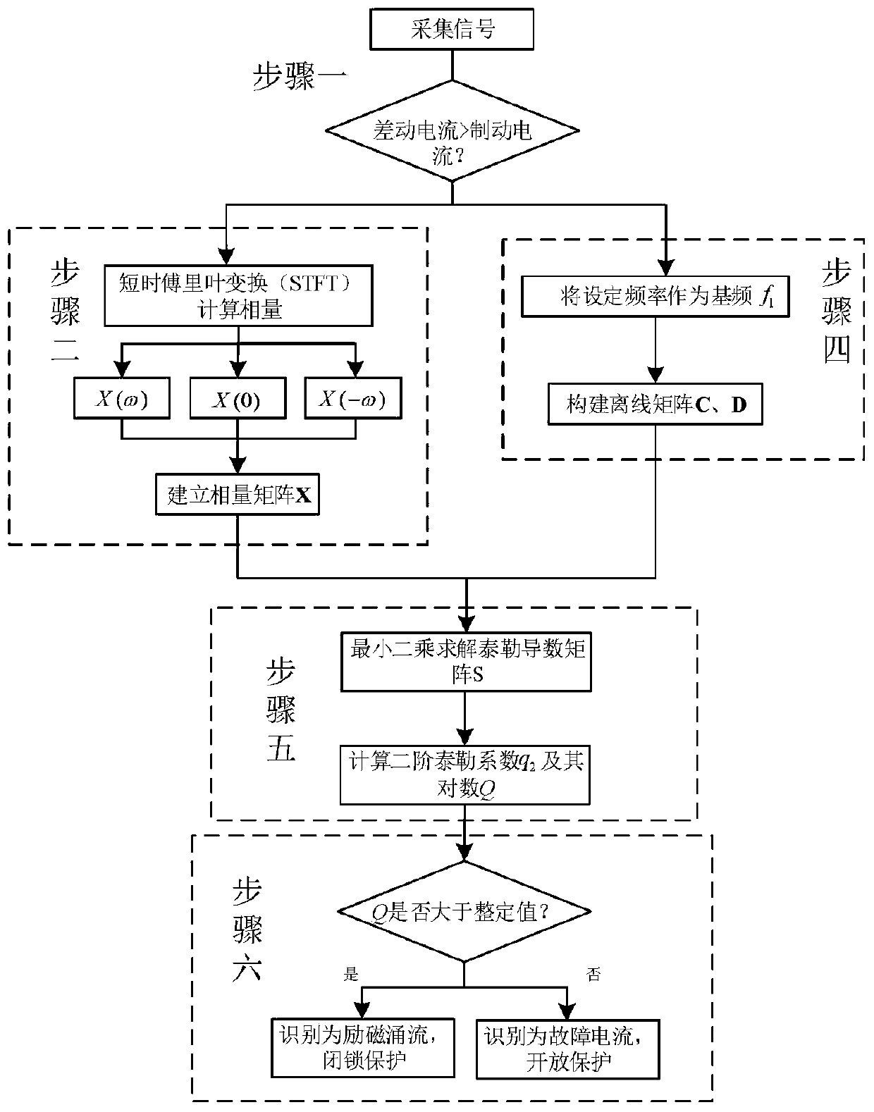
[0126] Such as Figure 1-2 As shown, a method for identifying inrush current based on the second-order Taylor coefficient includes the following steps:

[0127] Step 1: According to whether the differential current is greater than the braking current, judge whether there is a fault or a magnetizing inrush current;

[0128] Step 2: Perform short-time Fourier transform on the collected data to obtain reference time phasors X(-ω), X(0), X(ω);

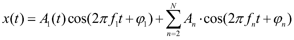
[0129] Step 3: Establish the phasor form of the simplified model of the inrush current, and use the Taylor expansion of the phasor model S(t) to obtain the Taylor derivative matrix S and the second-order Taylor coefficient q 2 and its logarithm Q;

[0130] Step 4: Use the set initial frequency as the fundamental frequency, and construct offline matrix C and offline matrix D according to the fundamental frequency;

[0131] Step 5: Input the data obtained in steps 3 and 4 into the Taylor dynamic model established in step 2 to solve the Ta...

Embodiment 2

[0155] Such as Figure 1-2 As shown, based on Example 1, step 3: the dynamic model of the inrush current is established by using the Taylor series to characterize the dynamic change characteristics of the second harmonic and the fundamental wave in the case of the inrush current, which better fits the inrush current in the actual power grid. Included dynamically changing properties. The part of the phasor model S(t) is expanded by Taylor to obtain the Taylor derivative matrix S. At the same time, the magnitude / phase angle model is used to carry out Taylor expansion on the exponent part of the phasor model S(t) to obtain the second-order Taylor coefficient q 2 and its logarithm Q. The second-order Taylor coefficient extracted from the dynamic model can reflect the electrical characteristics such as the second harmonic content and the change speed of the fundamental frequency component. This makes the present invention no longer rely on a single electrical quantity when ident...


PUM


Abstract

The invention discloses an excitation surge current recognition method based on a second-order Taylor coefficient, and relates to the field of power system relay protection and waveform recognition. The method comprises the following steps: step 1, judging whether a fault or magnetizing inrush current occurs according to whether a differential current is greater than a brake current; 2, performingshort-time Fourier transform on the acquired data to obtain a reference moment phasor; 3, establishing a phasor form of a magnetizing inrush current simplified model; 4, taking a set frequency initial value as a fundamental frequency, and constructing an offline matrix and an offline matrix according to the fundamental frequency; 5, inputting the data obtained in the steps 3 and 4 into the Taylordynamic model established in the step 2 to solve a Taylor derivative matrix, and solving a second-order Taylor coefficient and a logarithm Q thereof according to the Taylor derivative matrix; the method solves the problems that an existing magnetizing inrush current recognition method causes protection delay action and is poor in anti-noise capacity when a fault occurs, and achieves the effect ofaccurately and quickly judging the fault of the transformer in the locking period.

Description

technical field [0001] The invention relates to the field of relay protection and waveform identification of power systems, in particular to a second-order Taylor coefficient-based excitation inrush identification method. Background technique [0002] With the continuous development of the power grid, higher requirements are put forward for the reliability and quickness of transformer protection on site. For example, the Zhebei-Fuzhou-Zhefu 1000KV UHV AC transmission project has a transformation capacity of 1800WM, and the transformer protection involved Any abnormal behavior will lead to extremely serious consequences. However, in the voltage recovery process of transformer no-load closing or removing external faults, excitation inrush current may be generated, which may cause differential protection to malfunction. At present, the engineering site mainly relies on the second harmonic braking principle and discontinuous angle braking principle to identify the inrush curren...

Claims


Application Information

Patent Timeline
Patent Type & Authority Applications(China)
IPC IPC(8): G06F30/20G06F111/10G06F17/12G06F17/14G06F17/16G06Q50/06G01R31/00H02H7/045
CPCG01R31/00G06F17/12G06F17/142G06F17/16G06Q50/06H02H7/045
Inventor 符玲宋九渊王俊雄熊思宇麦瑞坤
Owner SOUTHWEST JIAOTONG UNIV
Why Eureka
Try Eureka