
Pixel drive circuit and display device

A technology of a pixel driving circuit and a driving unit, which is applied to static indicators, instruments, etc., can solve the problem of weak switching ability between high and low gray scales of the pixel driving circuit, and achieve the effect of improving the display effect and improving the switching ability.

Active Publication Date: 2020-01-17
SHENZHEN CHINA STAR OPTOELECTRONICS SEMICON DISPLAY TECH CO LTD
View PDF6 Cites 4 Cited by
  • Summary
  • Abstract
  • Description
  • Claims
  • Application Information

AI Technical Summary

Problems solved by technology

[0005] The disclosed embodiments provide a pixel driving circuit and a display device, which are used to solve the problem that the pixel driving circuit of a Micro-LED display device has a weak high-low grayscale switching capability

Method used


Image

  • Pixel drive circuit and display device
  • Pixel drive circuit and display device
  • Pixel drive circuit and display device

Examples


Embodiment Construction

[0031] The following descriptions of the various embodiments refer to the accompanying drawings to illustrate specific embodiments in which the present disclosure may be practiced. The directional terms mentioned in this disclosure, such as [top], [bottom], [front], [back], [left], [right], [inside], [outside], [side], etc., are for reference only The orientation of the attached schema. Therefore, the directional terms used are used to explain and understand the present disclosure, but not to limit the present disclosure. In the figures, structurally similar elements are denoted by the same reference numerals.

[0032] The disclosure will be further described below in conjunction with the accompanying drawings and specific embodiments:

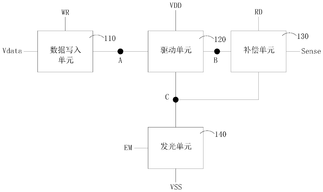
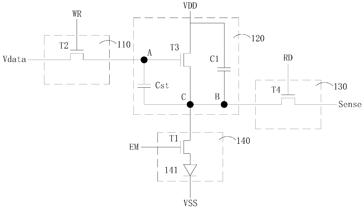
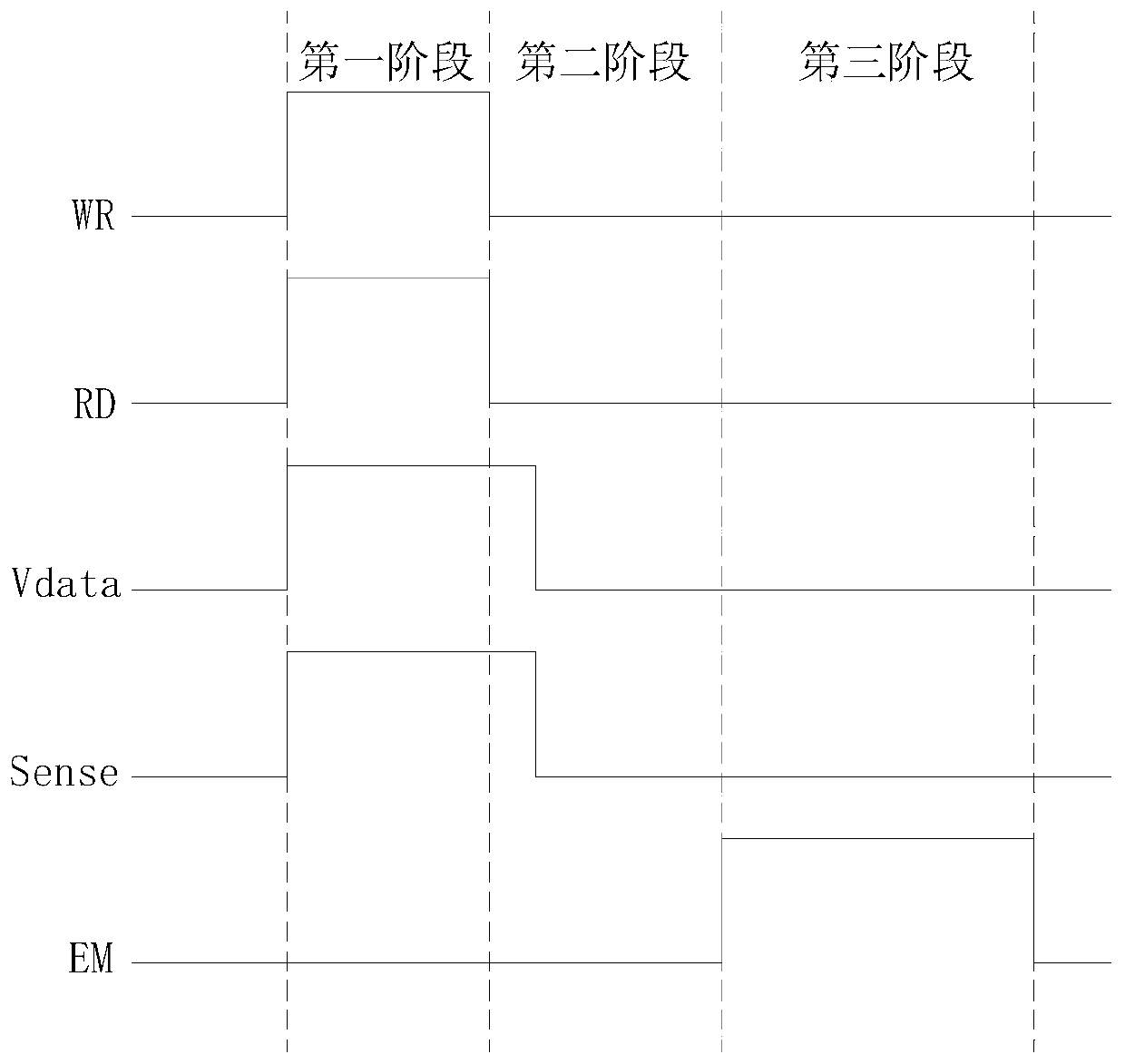
[0033] The disclosed embodiment provides a pixel driving circuit, which is combined with Figure 1 to Figure 3 Describe in detail.

[0034] Such as figure 1 as shown, figure 1 A schematic frame diagram of a pixel driving circuit provided...


PUM


Abstract

The invention provides a pixel drive circuit and a display device. The pixel drive circuit comprises a data writing unit, a driving unit, a compensation unit and a light-emitting unit. A first capacitor is added to a driving unit; the first end of the first capacitor is used for receiving the power supply high-voltage signal; the second end of the first capacitor is coupled with the second node; the first capacitor has a coupling effect on the driving unit; the data transmission efficiency of the driving unit in different gray scale states is reduced; high and low gray scales are switched through relatively low data transmission efficiency. Therefore, the switching capability of high and low gray scales of the pixel drive circuit is improved. Meanwhile, a first thin film transistor is additionally arranged between a micro light-emitting diode of the light-emitting unit and the driving unit; the grid electrode of the first thin film transistor is coupled with a light-emitting signal, and the drain electrode of the first thin film transistor is coupled with the first end of the micro light-emitting diode, thereby ensuring that the micro light-emitting diode is not affected by currentfluctuation of the driving unit before emitting light, and improving the display effect of the display device.

Description

technical field [0001] The present invention relates to the field of display technology, in particular to a pixel driving circuit and a display device. Background technique [0002] Micro Light Emitting Diode Display (Micro-LED) is a high-density integrated LED array display device. Compared with Liquid Crystal Display (Liquid Crystal Display, LCD) technology and Organic Light Emitting Diode (Organic Light -Emitting Diode, OLED) display device technology, Micro-LED has higher luminous efficiency and lower power consumption, and has the advantages of long life and fast response. [0003] The traditional 3T1C pixel driving circuit has been widely used in OLED displays. For the driving transistor, the magnitude of the current passing through the driving transistor determines the brightness of the OLED or Micro-LED, and the magnitude of the current is related to the gate and source of the driving transistor. The voltage difference Vgs is related, and the different magnitudes of...

Claims


Application Information

Patent Timeline
Patent Type & Authority Applications(China)
IPC IPC(8): G09G3/32
CPCG09G3/32G09G2310/0264G09G3/3233G09G2300/0852G09G2320/0233G09G2320/0295G09G3/2007G09G2310/027G09G2310/06G09G2320/0252
Inventor 张晓东韩佰祥
Owner SHENZHEN CHINA STAR OPTOELECTRONICS SEMICON DISPLAY TECH CO LTD
Learn More