
Travel switch buffer device

A cushioning device and travel switch technology, which is applied in the direction of the power device, electric switch, contact vibration/shock damping inside the switch, to achieve the effect of early buffering effect, good buffering effect, and guaranteed stability

Active Publication Date: 2020-01-17
江苏深盐达新能源科技有限公司
View PDF6 Cites 1 Cited by
  • Summary
  • Abstract
  • Description
  • Claims
  • Application Information

AI Technical Summary

Problems solved by technology

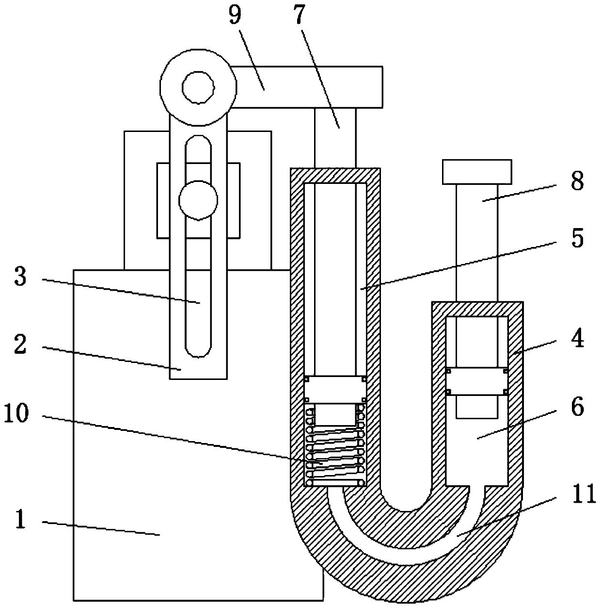
[0003] In view of the deficiencies in the use of the existing travel switch buffer device proposed in the background technology, the present invention provides a travel switch buffer device, which has the advantage of achieving a better buffer effect without affecting the movement of mechanical parts, and solves the problem of Problems raised in the background art above

Method used


Image

  • Travel switch buffer device
  • Travel switch buffer device

Examples


Embodiment Construction

[0014] The following will clearly and completely describe the technical solutions in the embodiments of the present invention with reference to the accompanying drawings in the embodiments of the present invention. Obviously, the described embodiments are only some, not all, embodiments of the present invention. Based on the embodiments of the present invention, all other embodiments obtained by persons of ordinary skill in the art without making creative efforts belong to the protection scope of the present invention.

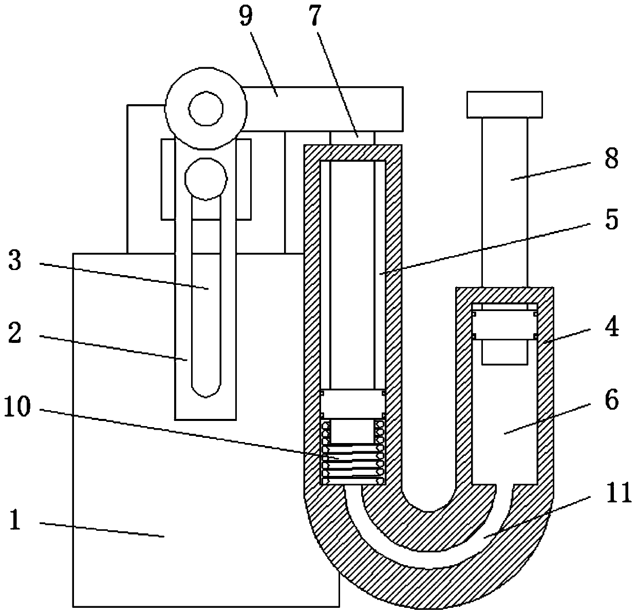
[0015] see Figure 1-2 , a stroke switch buffer device, including a base 1 and a striker 2, a chute 3 is opened on the front of the striker 2, a U-shaped tube 4 is provided on one side of the base 1, and the left and right sides of the inner cavity of the U-shaped tube 4 are respectively A buffer chamber 5 and a back pressure chamber 6 are provided, and the buffer chamber 5 and the back pressure chamber 6 are connected. The inside of the buffer chamber 5 and t...


PUM


Abstract

The invention relates to the technical field of detection instruments. The invention discloses a travel switch buffer device that comprises a base body and a firing pin; a U-shaped pipe is arranged onone side of the base body, a buffer cavity and a pressure return cavity are formed in the left side and the right side of an inner cavity of the U-shaped pipe correspondingly and communicate with each other, a buffer rod and a pressure return rod are slidably connected into the buffer cavity and the pressure return cavity correspondingly, and a connecting rod is fixedly connected to the end, extending out of the buffer cavity, of the buffer rod. The U-shaped pipe is arranged on one side of the firing pin; buffering can be achieved through hydraulic oil in the U-shaped pipe; the buffer rod isdriven by hydraulic oil; kinetic energy of a mechanical part is converted into kinetic energy of the pressure return rod; and then the pressure return rod reacts on the mechanical part, so that the buffering effect is achieved, the degree of dependence on the rigidity of the spring is small, a large buffering reaction force is generated only by utilizing the kinetic energy of the mechanical part when the mechanical part is close to a stop position, the good buffering effect is achieved, and normal movement of the mechanical part can be guaranteed.

Description

technical field [0001] The invention relates to the technical field of detection instruments, in particular to a travel switch buffer device. Background technique [0002] The travel switch, also known as the limit switch, is a kind of position switch. It uses the collision of the moving parts of the production machinery to make its contacts move to realize the connection or disconnection of the control circuit to achieve a certain control purpose. It usually includes a moving contact, a moving contact, a compression spring and a firing pin. After the firing pin is hit by the mechanical part, the firing pin will move along with the mechanical part. When the firing pin moves to the end point, the moving breaking contact conducts and makes The machine stops moving. At present, for the buffer device of the limit switch, it basically relies on the compression spring composed of the striker itself, that is, the compression spring not only undertakes the reset function of the str...

Claims


Application Information

Patent Timeline
Patent Type & Authority Applications(China)
IPC IPC(8): H01H3/16H01H3/24H01H3/60
CPCH01H3/16H01H3/24H01H3/605
Inventor 陈雪
Owner 江苏深盐达新能源科技有限公司
Learn More