
Multi-layer spliced drawing type comprehensive power distribution cabinet

A comprehensive power distribution cabinet and pull-out technology, applied in substation/distribution device housing, electrical components, substation/switch layout details, etc., can solve the difficulty of space layout, affect the long-term use of equipment, and poor internal ventilation problems, to achieve the effect of convenient installation and disassembly, convenient installation and use

Inactive Publication Date: 2020-01-17
JINAGSU HAIXIN ELECTRICAL EQUIP CO LTD
View PDF13 Cites 2 Cited by
  • Summary
  • Abstract
  • Description
  • Claims
  • Application Information

AI Technical Summary

Problems solved by technology

[0004] The purpose of the present invention is to provide a multi-layer spliced ​​pull-out integrated power distribution cabinet to solve the problem that the internal space of the existing integrated power distribution cabinet proposed in the above-mentioned background technology is mostly fixed, which leads to difficulties in spatial layout, and the During the working process of the device, the internal ventilation effect is not good, which affects the long-term use of the equipment

Method used


Image

  • Multi-layer spliced drawing type comprehensive power distribution cabinet
  • Multi-layer spliced drawing type comprehensive power distribution cabinet
  • Multi-layer spliced drawing type comprehensive power distribution cabinet

Examples


Embodiment Construction

[0027] The following will clearly and completely describe the technical solutions in the embodiments of the present invention with reference to the accompanying drawings in the embodiments of the present invention. Obviously, the described embodiments are only some, not all, embodiments of the present invention. Based on the embodiments of the present invention, all other embodiments obtained by persons of ordinary skill in the art without making creative efforts belong to the protection scope of the present invention.

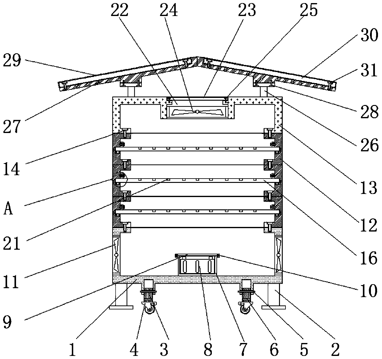
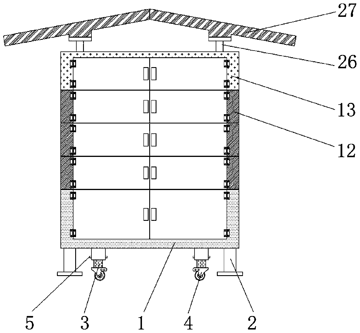
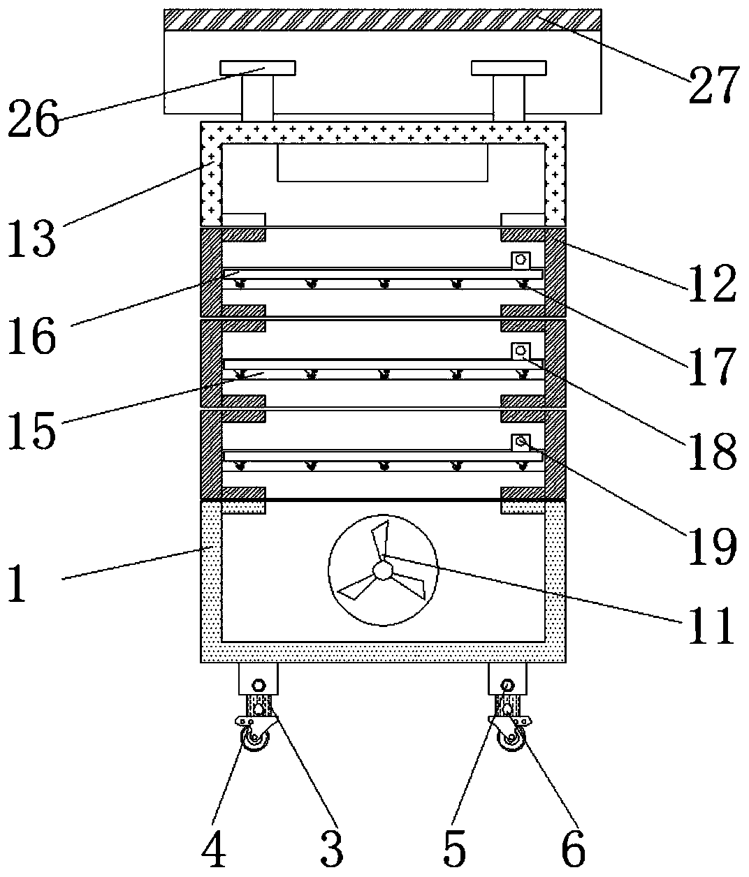
[0028] see Figure 1-6 , the present invention provides a technical solution: a multi-layer spliced ​​pull-out integrated power distribution cabinet, according to figure 1 and figure 2 As shown, brackets 2 are fixed on the left and right sides of the bottom of the bottom cabinet 1, and the inner side of the bracket 2 is provided with a moving column 3. One roller 4, while the moving column 3 is fixed on the base cabinet 1 through the first latch 5, the firs...


PUM


Abstract

The invention discloses a multi-layer spliced drawing type comprehensive power distribution cabinet that comprises a bottom cabinet, storage plates, second rolling wheels, a bearing frame and a bearing plate; a movable column is connected to the lower end surface of the bottom cabinet in a clamping manner; a bearing box is fixed at the inner bottom of the bottom cabinet; first fans are arranged onthe left side, the right side and the rear side of the bottom cabinet; splicing frames are connected through second bolts, the splicing frames and the bottom cabinet are connected through second bolts, and the splicing frames and a top cabinet are connected through second bolts. The left side and the right side of the storage plate and the second rolling wheels are arranged in sliding grooves, fixing blocks are fixed to the upper end face of the storage plate, mounting holes are formed in the upper end face of the storage plate, a through hole is formed in the top of the top cabinet, and a clamping groove is formed in the bearing plate. According to the multi-layer spliced drawing type comprehensive power distribution cabinet, the corresponding number of splicing frames can be installed between the bottom cabinet and the top cabinet according to specific requirements, and the splicing frames can be fixed by screwing down the second bolts, so that subsequent installation and use of thestorage plates are facilitated.

Description

technical field [0001] The invention relates to the technical field of integrated power distribution cabinets, in particular to a multi-layer spliced ​​pull-out integrated power distribution cabinet. Background technique [0002] Integrated power distribution cabinet is a new type of integrated control box that integrates power distribution, measurement, protection, control, and reactive power compensation. It is widely used in substations, factories, industrial and mining enterprises, large power plants, petroleum, chemical enterprises, large steel mills, High-rise building power center, reactive power compensation, metering, power distribution and other occasions. [0003] The internal space of the existing integrated power distribution cabinet is mostly fixed, which leads to difficulty in space layout, and the internal ventilation effect of the device is not good during the working process, which affects the long-term use of the equipment, so it is not convenient to use. ...

Claims


Application Information

Patent Timeline
IPC IPC(8): H02B1/30H02B1/36H02B1/56H02B1/28
CPCH02B1/28H02B1/30H02B1/36H02B1/565
Inventor 张鹏王万年
Owner JINAGSU HAIXIN ELECTRICAL EQUIP CO LTD
Learn More