
Gas generator and assembly method for dual-type gas generator

A technology of gas generators and gas generating agents, which is applied in the fields of weapon accessories, transportation and packaging, and vehicle safety arrangements, and can solve problems such as pulverization of gas generating agents, sound generation, and changes in combustion characteristics of gas generating agents.

Active Publication Date: 2020-01-17
DAICEL CHEM IND LTD
View PDF8 Cites 0 Cited by
  • Summary
  • Abstract
  • Description
  • Claims
  • Application Information

AI Technical Summary

Problems solved by technology

However, when the gas generating agent is filled in a metal case, if the gas generating agent moves unnecessarily in the case, the gas generating agent may be pulverized by contact with the case.
Compared with before pulverization, the gas generant surface area of ​​the pulverized gas generant increases, so the combustion characteristics of the gas generant change, and the combustion of the gas generant as designed may not be obtained
In addition, such unnecessary movement of the gas generating agent may also be a cause of sound during vibration

Method used


Image

  • Gas generator and assembly method for dual-type gas generator
  • Gas generator and assembly method for dual-type gas generator
  • Gas generator and assembly method for dual-type gas generator

Examples


Embodiment 1

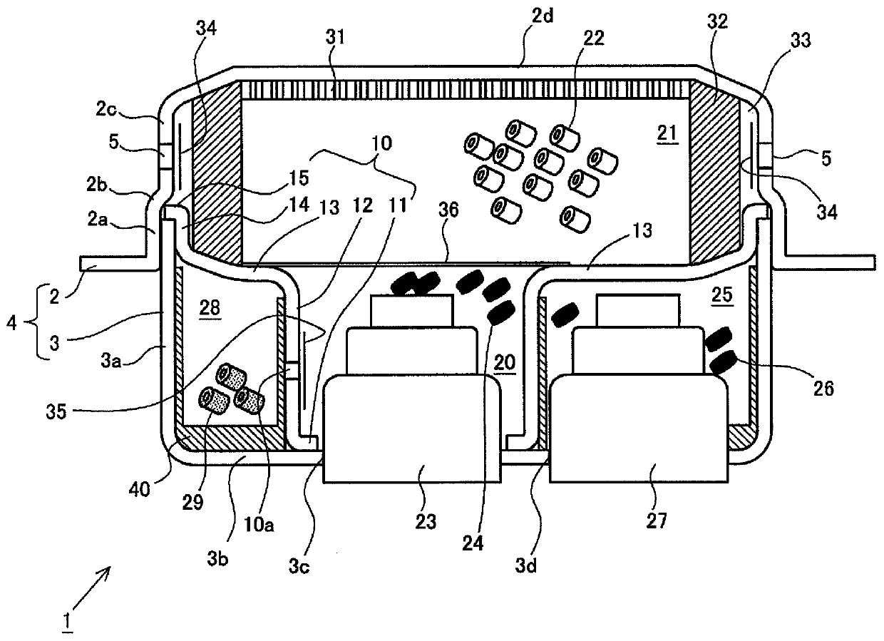
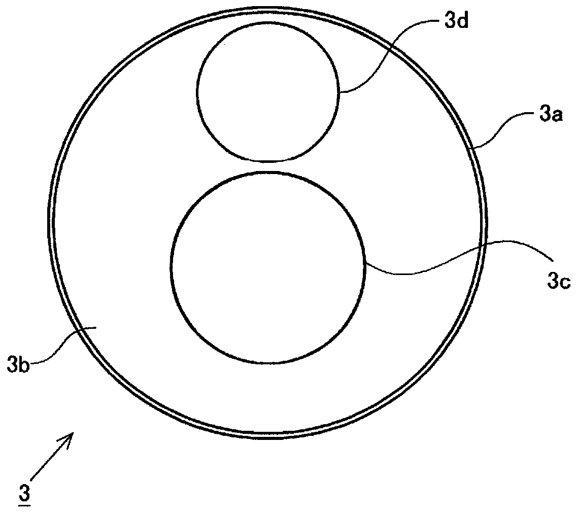
[0066] figure 1 is a cross-sectional view of the gas generator 1 in the height direction, figure 2 It is a plan view of the lower case 3 (second case) included in the gas generator 1 . The gas generator 1 is configured to burn a gas generating agent filled in a casing 4 formed of an upper casing 2 (first casing) and a lower casing 3 to release combustion gas. The gas generator 1 is a so-called two-stage gas generator in which two combustion chambers are arranged vertically as described later, and a corresponding igniter and a gas generating agent are arranged in each combustion chamber. Here, the upper case 2 has a peripheral wall portion 2c and a top portion 2d, and a concave internal space is formed by these. The top surface portion 2d and the bottom surface portion 3b of the lower case 3 described later have a substantially circular shape in plan view, and the peripheral wall portion 2c and the peripheral wall portion 3a of the lower case 3 described later surround the t...


PUM


Abstract

The present invention provides a gas generator. The gas generator comprises: a metal housing which accommodates an igniter and in which a gas discharge port is formed, the housing including a combustion chamber in which a solid gas generating agent, loaded at a location where combustion can occur, is combusted due to the action of the igniter; and a separating member, interposed in the interior ofthe housing between the gas generating agent arranged in the combustion chamber and a base surface and a side surface of the combustion chamber, the separating member including a separating wall formed from a prescribed resin material so as to be in contact with the gas generating agent and to impart a prescribed retaining force to the gas generating agent. Due to this configuration, powdering ofthe gas generating agent loaded into the housing of the gas generator and vibration noise are suppressed.

Description

technical field [0001] The present invention relates to a gas generator that burns a gas generating agent by the operation of an igniter to generate combustion gas. Background technique [0002] In a gas generator that generates combustion gas by burning the gas generating agent filled in the combustion chamber by the operation of the igniter, if the filled gas generating agent does not burn as expected, it is difficult to generate combustion gas as designed. Here, in order to withstand the pressure generated by the combustion of a gas generating agent, the casing of a gas generator is usually made of metal. However, when the gas generating agent is filled in the metal casing, if the gas generating agent moves unnecessarily inside the casing, the gas generating agent may be pulverized by contact with the casing. Since the gas generant surface area of ​​the gas generant after pulverization is increased compared with that before pulverization, the combustion characteristics o...

Claims


Application Information

Patent Timeline
Patent Type & Authority Applications(China)
IPC IPC(8): B60R21/26B60R21/264
CPCB60R21/26B60R21/264F42B3/04B60R21/235B60R2021/26029B60R2021/23528B60R2021/23519
Inventor 山本纮士薮田干夫
Owner DAICEL CHEM IND LTD
Learn More