Three-jaw chuck with adjustable auxiliary supporting structure and using method for three-jaw chuck

A three-jaw chuck and auxiliary support technology, which is applied in the direction of chucks, tool holder accessories, metal processing equipment, etc., can solve the problems of insufficient rigidity in the cutting area, increase the rigidity of the cutting area, and deformation of parts during processing, so as to improve cutting conditions. , multi-cutting force, and stable cutting process

Inactive Publication Date: 2020-01-21
XIAN AEROSPACE PROPULSION TESTING TECH RES INST
View PDF5 Cites 1 Cited by
  • Summary
  • Abstract
  • Description
  • Claims
  • Application Information

AI Technical Summary

Problems solved by technology

In the cutting process, a 15-inch chuck is used to process the small end of the clamping Φ100. In addition to controlling the clamping force for clamping, the problem in actual processing is that the clamping area and the cutting area are not in the same area, and a certain amount of time must be passed. Measures and methods to increase the rigidity of the cutting area
[0004] When the small end of the existing three-jaw chuck is used to process the large end of the part, the rigidity of the cutting area is insufficient, which may easily cause the processing deformation of the part, so it is necessary to design a reliable auxiliary support device; according to the different supporting parts, it is necessary to be able to adjust the position of the auxiliary support , and the support height can be adjusted

Method used


Image

  • Three-jaw chuck with adjustable auxiliary supporting structure and using method for three-jaw chuck
  • Three-jaw chuck with adjustable auxiliary supporting structure and using method for three-jaw chuck
  • Three-jaw chuck with adjustable auxiliary supporting structure and using method for three-jaw chuck

Examples


Embodiment 1

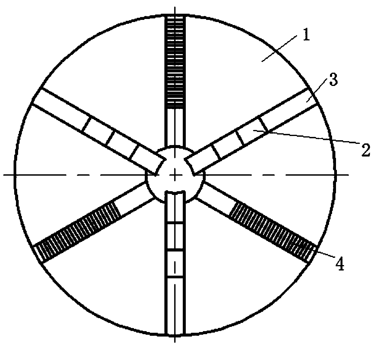
[0037] refer to figure 1 and figure 2 , is a structural schematic diagram of Embodiment 1 of the present invention, a three-jaw chuck with an adjustable auxiliary support structure, which is characterized in that it includes:

[0038] The chuck body 1 has a chuck hole in the middle center of the chuck body 1;

[0039] There are three soft-jaw slots 3 along the chuck hole in the center of the chuck body 1, and the three soft-jaw slots 3 are evenly distributed on the upper surface of the chuck body 1;

[0040] The soft jaw 2 is detachably connected in the soft jaw slot 3 along the chuck hole;

[0041] The support column tooth groove 4, the support column tooth groove 4 is arranged between two adjacent soft claw slots 3, and there are three support column tooth grooves 4;

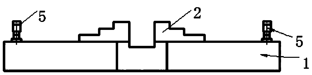
[0042] The support column 5 is detachably connected in the support column tooth groove 4 .

[0043] In actual use: put the machined part into the chuck hole at the center of the middle of the chuck body 1...

Embodiment 2

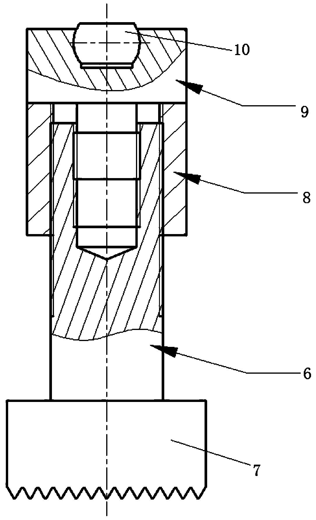
[0045] refer to image 3 , Compared with Embodiment 1, the difference of this embodiment is that: the support column 5 includes a support stud base 7, a support stud 6, a lock nut 8 and a support head 9, and the support stud 6 is connected to The top of the support stud base 7, the lock nut 8 is connected to the outer wall of the support stud 6, the support head 9 is connected to the top of the support stud 6, and the support head 9 is located above the lock nut 8, the support column tooth groove 4 Internal teeth are arranged inside, and the bottom of the support stud base 7 is connected in the support column tooth groove 4 .

[0046] In actual use: when adjusting the support column 5, first adjust the height of the support head 9 at the top of the support stud 6, and after determining the height of the support head 9, adjust the position of the support head 9 on the other two support columns 5. Adjust to make the processing surface of the processed parts level, and then scre...

Embodiment 3

[0048] Compared with Embodiment 2, the difference of this embodiment is that: the top of the support stud 6 has a threaded hole, the support head 9 is a screw-shaped structure, and the support head 9 is screwed on the support screw through the threaded hole. Top of column 6.

[0049] In actual use: when adjusting the support column 5, first adjust the height of the entire machined part by screwing the height of the screw-shaped support head 9 in the top threaded hole of the support stud 6, so as to adjust to the level of the machined surface of the machined part, use The height adjustment operation of the structure is simple, and the adjustment is convenient and fast.


PUM


Abstract

The invention relates to the technical field of machining, in particular to a three-jaw chuck with an adjustable auxiliary supporting structure and a using method for the three-jaw chuck. A machined part is placed in a chuck hole formed in the center of the middle part of a chuck body and is then supported and clamped by the soft jaws in three soft jaw clamping grooves, supporting columns, heightsof which can be adjusted up and down, are put in supporting column gear grooves respectively and are adjusted to leveling the machining surface of the machined part, and finally the machining part ismachined. Through the three-jaw chuck of the structure, the auxiliary supporting position and the supporting height can be adjusted, so that the rigidity of a cutting system is improved, the system can bear more cutting force, the cutting condition is improved, and the cutting process is more stable.

Description

[0001] Technical field [0002] The invention relates to the technical field of mechanical processing, in particular to a three-jaw chuck with an adjustable auxiliary support structure and a use method thereof. Background technique [0003] The ignition device of a certain type of solid rocket motor has a thin-walled ring-shaped aluminum alloy structure. The outer diameter of the ring is Φ460mm, and the wall thickness of the ring is 2mm. During cutting, it is necessary to clamp the small end of Φ100mm and process the large end of Φ460mm. In the cutting process, a 15-inch chuck is used to process the small end of the clamping Φ100. In addition to controlling the clamping force for clamping, the problem in actual processing is that the clamping area and the cutting area are not in the same area, and a certain amount of time must be passed. Measures and methods to increase the rigidity of the cutting area. [0004] When the small end of the existing three-jaw chuck is used to p...

Claims


Application Information

Patent Timeline
Patent Type & Authority Applications(China)
IPC IPC(8): B23B31/103
CPCB23B31/103B23B2231/34
Inventor 周峰王亮李琪李卫东田江涛夏可明苏景亮厍黎明
Owner XIAN AEROSPACE PROPULSION TESTING TECH RES INST
Why Eureka
Try Eureka