Thin-wall cavity part machining rigid supporting method

A part processing and rigid support technology, which is applied in the direction of metal processing equipment, metal processing machinery parts, supports, etc., can solve the problem of dimensional tolerance and shape tolerance of thin-walled cavity parts not meeting requirements, precision errors, low production efficiency, etc. question

Active Publication Date: 2020-01-21
GUIZHOU AEROSPACE NANHAI SCI & TECH
View PDF6 Cites 3 Cited by
  • Summary
  • Abstract
  • Description
  • Claims
  • Application Information

AI Technical Summary

Problems solved by technology

[0002] In order to reduce the weight of the equipment, parts with large dimensions are usually designed as thin-walled cavity parts. For parts with dimensional tolerance and shape tolerance requirements on the outside of the cavity and the part, in the process of processing the outside of the part, due to the thin-walled cavity The thickness of the cavity part is small, and the outer wall of the thin-walled cavity part will vibrate, resulting in deformation of the part, resulting in the dimensional tolerance and shape tolerance of the processed thin-walled cavity part not meeting the requirements
[0003] To reduce the vibration of thin-walled cavity parts, it is necessary to support the inside of the cavity. If the tooling is directly used for support, there is also an accuracy error in tooling processing, and it will not be able to support the cavity if it cannot be completely fitted. Therefore, At present, the commonly used method is to fill the cavity of thin-walled cavity parts with paraffin wax. Although this solution solves the vibration of thin-walled cavity parts during processing, paraffin cannot form a rigid support for the cavity of thin-walled cavity parts. Press and hold the thin-walled cavity parts, so that when the outer plane of the thin-walled cavity parts is processed, the thin-walled cavity parts can only be processed with a small amount of multiple feeds, resulting in low production efficiency and high production costs

Method used


Image

  • Thin-wall cavity part machining rigid supporting method
  • Thin-wall cavity part machining rigid supporting method
  • Thin-wall cavity part machining rigid supporting method

Examples


Embodiment Construction

[0026] The technical solution of the present invention is further described below, but the scope of protection is not limited to the description.

[0027] Such as Figure 1 to Figure 8 shown.

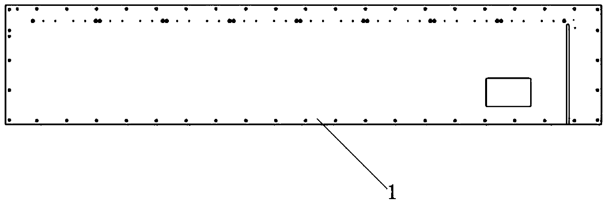
[0028] A method for processing rigid supports for thin-walled cavity parts of the present invention comprises the following steps:

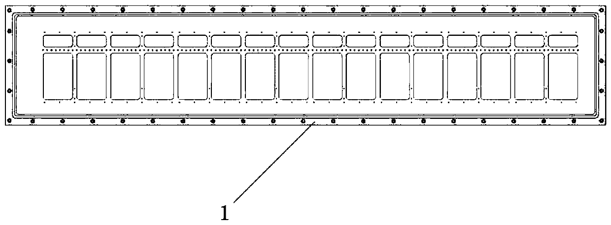
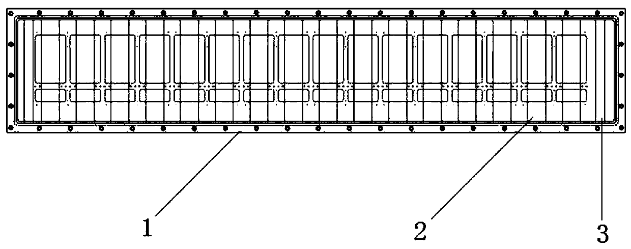
[0029] Step 1: Install flexible base layer A2 and base layer B3 on each cavity and both ends of the thin-walled cavity part 1;

[0030] Step 2: apply a curing agent on the base layer A2 and the base layer B3 respectively to form a cured layer A4 and a cured layer B5;

[0031] Step 3: Install several supporting tooling parts A6 and at least two supporting tooling parts B7 on the curing layer A4 and curing layer B5 respectively, so that the curing layer A4 and curing layer B5 are naturally dried under natural conditions, and the two supporting tooling parts Part B7 is installed on both sides of the cavity of the thin-wall cavity part 1 respectively.

[0...


PUM


Abstract

The invention discloses a thin-wall cavity part machining rigid supporting method. The thin-wall cavity part machining rigid supporting method comprises the following steps: (1) flexible basal body layers A and basal body layers B are mounted in each molding cavity and at the two ends of thin-wall cavity parts; (2) curing agents are coated on the basal body layers A and the basal body layers B toform curing layers A and curing layers B; and (3) multiple supporting tool pieces A and at least two supporting tool pieces B are correspondingly mounted on the curing layers A and the curing layers B, so that the curing layers A and the curing layers B are naturally dried under natural conditions. Under the effects of the multiple supporting tool pieces A and the two supporting tool pieces B, thethin-wall cavity parts are rigidly supported, so that the vibration phenomenon is solved, and the dimensional tolerance and the form and location tolerance of the machined thin-wall cavity parts meetthe requirements.

Description

technical field [0001] The invention belongs to the technical field of processing thin-walled cavity parts, and relates to a rigid support method for processing thin-walled cavity parts. Background technique [0002] In order to reduce the weight of the equipment, parts with large dimensions are usually designed as thin-walled cavity parts. For parts with dimensional tolerance and shape tolerance requirements on the outside of the cavity and the part, in the process of processing the outside of the part, due to the thin-walled cavity The thickness of the cavity part is small, and the outer wall of the thin-walled cavity part will vibrate, resulting in deformation of the part, resulting in the dimensional tolerance and shape tolerance of the processed thin-walled cavity part not meeting the requirements. [0003] To reduce the vibration of thin-walled cavity parts, it is necessary to support the inside of the cavity. If the tooling is directly used for support, there is also ...

Claims


Application Information

Patent Timeline
Patent Type & Authority Applications(China)
IPC IPC(8): B23Q3/00
CPCB23Q3/00
Inventor 何环
Owner GUIZHOU AEROSPACE NANHAI SCI & TECH
Why Eureka
Try Eureka