
Dry floor liquid disposal system

A technology for drying floors and floors, which is applied to aircraft floors, carpets, floors, etc., and can solve problems such as negative impact on flight experience

Pending Publication Date: 2020-01-21
THE BOEING CO
View PDF21 Cites 0 Cited by
  • Summary
  • Abstract
  • Description
  • Claims
  • Application Information

AI Technical Summary

Problems solved by technology

As a result, the flying experience of individuals on board the aircraft may be negatively affected

Method used


Image

  • Dry floor liquid disposal system
  • Dry floor liquid disposal system
  • Dry floor liquid disposal system

Examples


Embodiment Construction

[0024] The foregoing summary, as well as the following detailed description of certain embodiments, are better understood when read in conjunction with the accompanying drawings. As used herein, an element or step in the singular and preceded by the word "a" or "an" should be understood as not necessarily excluding a plurality of elements or steps. Furthermore, references to "one embodiment" are not intended to be interpreted as excluding the existence of additional embodiments that also incorporate the recited features. Furthermore, an embodiment that "comprises" or "has" one or more elements with a specified condition may include additional elements that do not have that condition unless expressly stated to the contrary.

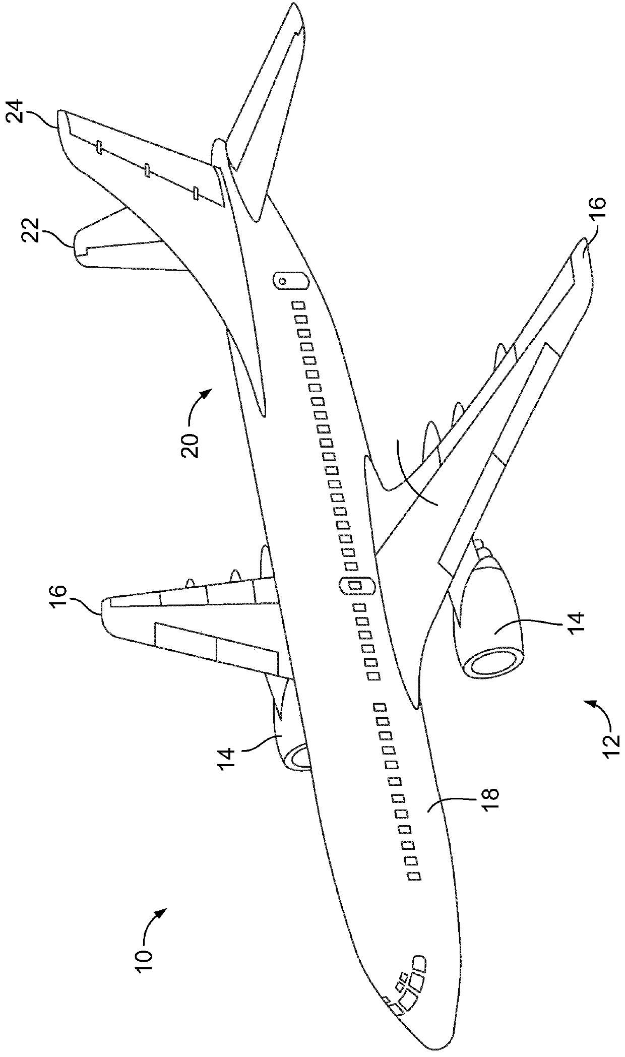
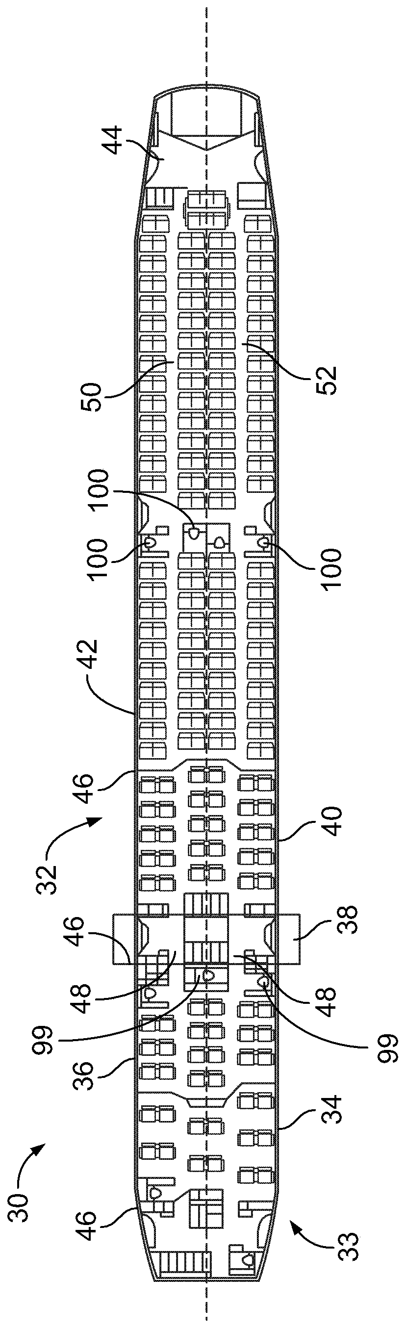
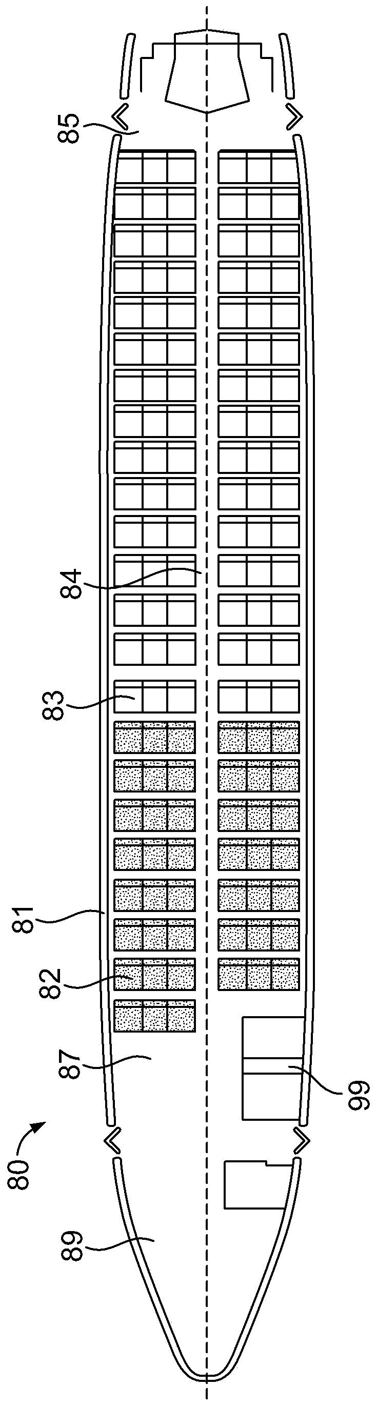
[0025] Embodiments of the present disclosure provide systems, methods, and assemblies for providing dry floors, such as lavatory floors. The systems, methods, and assemblies may be used in various settings, such as in a vehicle's lavatory, public restroom...


PUM


Abstract

The invention relates to a dry floor liquid disposal system. A dry floor assembly is provided. The dry floor assembly is configured to form or be positioned on a floor of an enclosed space. The dry floor assembly includes a grid, a pan, and a wicking layer. The grid has an array of openings configured to allow passage of liquid. The grid has members that extend from a base to an upper surface, with the upper surface configured to be walked upon. The members have a cross-section that tapers from the base to the upper surface. The pan is disposed beneath the grid, and defines a cavity. The wicking layer is interposed between the pan and the grid, and is configured to wick liquid that passes through the openings toward the pan.

Description

[0001] related application [0002] This application is related to and claims priority to U.S. Provisional Patent Application No. 62 / 697,727, filed July 13, 2018, entitled "Dry Floor Liquid Disposal System," which is incorporated herein by reference in its entirety. technical field [0003] Embodiments of the present disclosure generally relate to systems and methods for providing floors for collecting and / or removing liquids, such as lavatory floors within commercial aircraft. Background technique [0004] In various environments, floors may be subject to spills or leaks of liquids. It may not be possible or practical to manually remove the liquid from the floor in the short amount of time that may be required. For example, commercial aircraft are used to transport passengers between locations. During flights, especially transoceanic or other long-distance flights, passengers are often confined to certain areas of the aircraft (eg, the cabin). Various individuals (eg, pa...

Claims


Application Information

Patent Timeline
Patent Type & Authority Applications(China)
IPC IPC(8): B64C1/18B64D11/02
CPCE04F15/02172B64C1/18B64D11/02A47G27/0225B32B5/02B32B17/06B32B2307/726B64C2211/00E04B5/48E04F15/18
Inventor J·J·柴尔德里斯
Owner THE BOEING CO
Features
  • Generate Ideas
  • Intellectual Property
  • Life Sciences
  • Materials
  • Tech Scout
  • Unparalleled Data Quality
  • Higher Quality Content
  • 60% Fewer Hallucinations
Learn More