
Flaw detection device for shielding tank

A technology of flaw detection device and shielding tank, which is applied in the direction of measuring device, workpiece clamping device, instrument, etc., can solve the problems of high labor intensity, heavy shielding tank, low efficiency, etc., and achieve the effect of convenient detection and high work efficiency

Pending Publication Date: 2020-01-21
大冶市探伤机有限责任公司
View PDF0 Cites 0 Cited by
  • Summary
  • Abstract
  • Description
  • Claims
  • Application Information

AI Technical Summary

Problems solved by technology

[0003] Due to the heavy weight of the shielding tank, the traditional detection method is to carry out detection by manpower, which is inefficient and labor-intensive

Method used


Image

  • Flaw detection device for shielding tank
  • Flaw detection device for shielding tank
  • Flaw detection device for shielding tank

Examples


Embodiment Construction

[0019] The principles and features of the present invention are described below in conjunction with the accompanying drawings, and the examples given are only used to explain the present invention, and are not intended to limit the scope of the present invention.

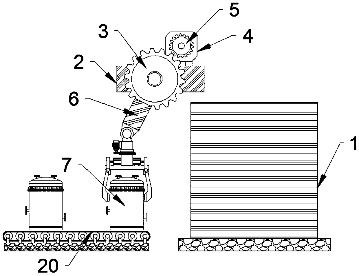
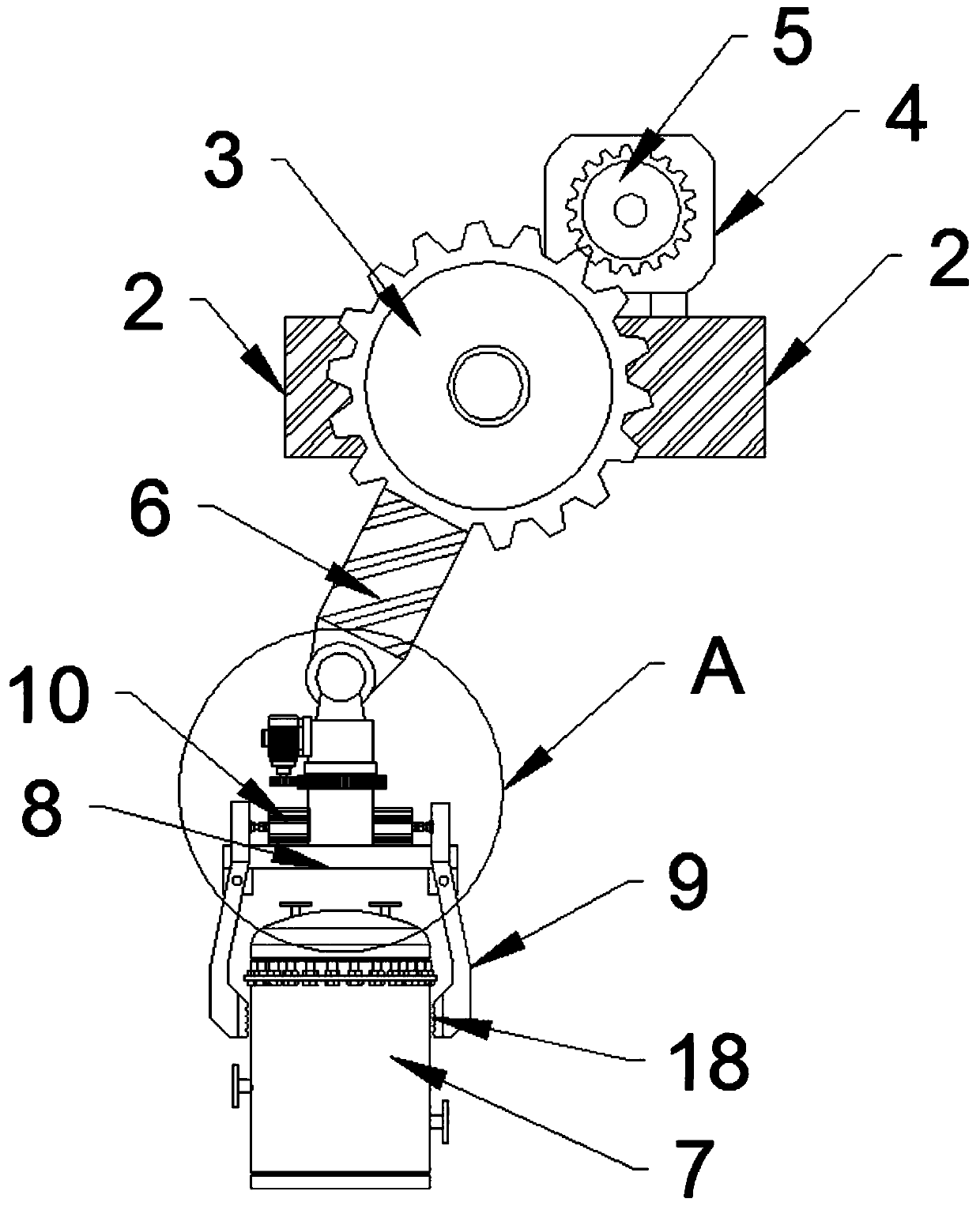
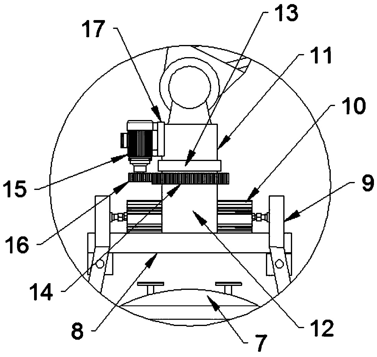
[0020] like figure 1 , figure 2 , image 3 , Figure 4 As shown, a flaw detection device for a shielding tank includes a flaw detection box 1, a top bracket 2 is arranged on the upper side of the flaw detection box 1, and a first motor 4 is installed on the top side of the top bracket 2. The first driving gear 5 is installed on the output shaft of the first motor 4, and the side of the top bracket 2 is equipped with a speed change gear 3. The first drive gear 5 meshes with the speed change gear 3. The number of teeth is suitable for decelerating and improving the torque of the transmission gear 3. The speed change gear 3 is fixed with a swing arm 6, and the lower end of the swing arm 6 is hinged with a fixed sh...


PUM


Abstract

The invention relates to a flaw detection device for a shielding tank. The flaw detection device comprises a flaw detection box, wherein a top bracket is arranged on the upper side of the flaw detection box; a first motor is mounted on the upper side of the top bracket; a first driving gear is mounted on an output shaft of the first motor; a speed change gear is mounted on the side surface of thetop bracket; the first driving gear is meshed with the speed change gear; a swing arm is fixed on the speed change gear; the lower end of the swing arm is hinged with a fixed shaft; the lower end of the fixed shaft is movably connected with a movable shaft; a rotating gear is arranged outside the movable shaft in a sleeving manner; a second motor is mounted on the side surface of the fixed shaft;a second driving gear is mounted on an output shaft of the second motor; the second driving gear is meshed with the rotating gear; a cross arm is fixed at the lower end of the movable shaft; clampingarms are hinged to two ends of the cross arm; hydraulic cylinders are mounted on two sides of the movable shaft; and movable shaft ends of the hydraulic cylinders are hinged with the upper ends of theclamping arms. The flaw detection device for the shielding tank is high in working efficiency and convenient in detection.

Description

technical field [0001] The invention relates to the technical field of shielding tank detection, in particular to a flaw detection device for shielding tanks. Background technique [0002] Nuclear power plants will produce some radioactive liquid waste during normal operation, including expected operational events, which need to be treated to protect the ecological environment, so that the radioactive level is lower than the allowable value of environmental discharge. When storing the radioactive waste liquid, a shielding tank is required for storage, and the shielding tank can effectively shield the nuclear waste liquid from external radiation. In order to ensure that the shielding effect of the shielding tank meets the standard, it must be tested for flaw detection before leaving the factory to avoid harm to animals and the surrounding environment. [0003] Due to the heavy weight of the shielding tank, the traditional detection method is to carry out detection by manpowe...

Claims


Application Information

Patent Timeline
IPC IPC(8): G01D11/00B25B11/00
CPCB25B11/00G01D11/00
Inventor 吴迁刘佳明
Owner 大冶市探伤机有限责任公司
Learn More