
Projector

A projector and limit slot technology, applied in the field of projectors, can solve the problems of inability to protect the lens, loss, etc., and achieve the effect of simple and fast fixed installation and convenient connection

Inactive Publication Date: 2020-01-21
杭州兔研工业设计有限公司
View PDF0 Cites 2 Cited by
  • Summary
  • Abstract
  • Description
  • Claims
  • Application Information

AI Technical Summary

Problems solved by technology

[0004] The purpose of the present invention is to provide a projector to solve the problem that the existing lens protective cover and the projector proposed in the above-mentioned background technology are not of an integrated structure. Only then can the projector be used. Because the lens protective cover is separated from the projector, it is very likely that it will be lost, resulting in the inability to protect the lens. Even if you can buy a new protective cover, it will take a certain amount of time.

Method used


Image

  • Projector
  • Projector
  • Projector

Examples


Embodiment 1

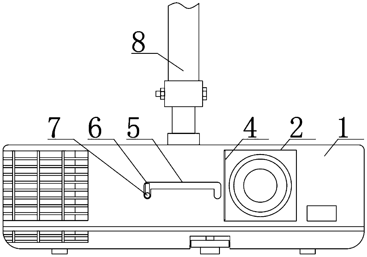
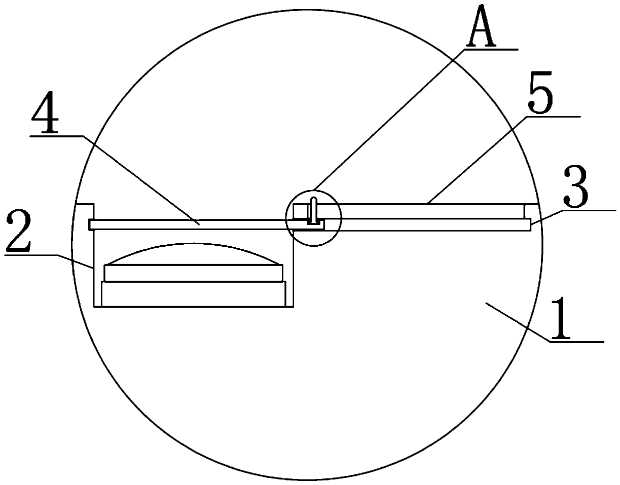
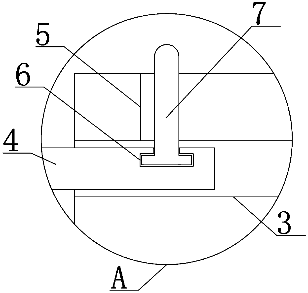
[0025] see Figure 1 to Figure 3 , the present invention provides a technical solution: a projector, including a projector 1, the surface of the projector 1 is provided with a lens groove 2, one side of the lens groove 2 is provided with a built-in groove 3, and the inside of the built-in groove 3 is provided with a protective cover 4 , the protective cover 4 is slidingly connected with the built-in groove 3, the inner wall of the built-in groove 3 is penetrated with a chute 5 to the outside of the projector 1, the surface of the protective cover 4 is provided with a moving groove 6, and the inside of the moving groove 6 is provided with a movable Toggle lever 7, and the toggle lever 7 is engaged with the chute 5. Through the designed structure of the present invention, when the projector 1 is not in use, the designed chute 5, the moving groove 6 and the toggle lever 7 can be conveniently The protective cover 4 is removed from the built-in groove 3, so as to protect the lens o...

Embodiment 2

[0027] see Figure 1 to Figure 7 , the present invention provides a technical solution: a projector, including a projector 1, the surface of the projector 1 is provided with a lens groove 2, one side of the lens groove 2 is provided with a built-in groove 3, and the inside of the built-in groove 3 is provided with a protective cover 4 , the protective cover 4 is slidingly connected with the built-in groove 3, the inner wall of the built-in groove 3 is penetrated with a chute 5 to the outside of the projector 1, the surface of the protective cover 4 is provided with a moving groove 6, and the inside of the moving groove 6 is provided with a movable Toggle lever 7, and the toggle lever 7 is engaged with the chute 5. Through the designed structure of the present invention, when the projector 1 is not in use, the designed chute 5, the moving groove 6 and the toggle lever 7 can be conveniently The protective cover 4 is removed from the built-in groove 3, so as to protect the lens o...


PUM


Abstract

The invention discloses a projector, which includes a projector. A surface of the projector is provided with a lens slot. A side of the lens slot is provided with a built-in slot. Inside the built-inslot, a protective cover is disposed and is in sliding connection with the built-in slot. The inner wall of the built-in slot is provided with a sliding slot penetrating to the outer side of the projector. The surface of the protective cover is provided with a moving slot. A movable toggle lever is disposed inside the moving slot. The toggle lever is engaged with the sliding slot. The designed structure of the present invention allows the protective cover to be easily removed from the built-in slot through the designed sliding slot, the moving slot, and the toggle lever when the projector is not in use, thereby protecting a projector lens. Compared with the prior art, the projector avoids lossing the protective cover, and allows the protective cover and the lens slot to be conveniently connected.

Description

technical field [0001] The invention belongs to the technical field of projectors, and in particular relates to projectors. Background technique [0002] A projector, also known as a projector, is a device that can project images or videos onto a screen. It can be connected to a computer, VCD, DVD, BD, game console, DV, etc. through different interfaces to play the corresponding video signal. [0003] There are still some deficiencies in existing projectors in use: the existing lens protective cover and the projector are not integral structures, and when using the projector, the lens protective cover that is engaged with the projector lens needs to be removed. Only then can the projector be used. Because the lens protective cover is separated from the projector, it is very likely that it will be lost, resulting in the inability to protect the lens. Even if you can buy a new protective cover, it will take a certain amount of time. Contents of the invention [0004] The pur...

Claims


Application Information

Patent Timeline
Patent Type & Authority Applications(China)
IPC IPC(8): G03B21/14
CPCG03B21/145
Inventor 陈云岳
Owner 杭州兔研工业设计有限公司
Learn More