
Power distribution network ground potential live line connection T wiring device

A wiring device, ground potential technology, applied in conductive connection, electrical component connection, circuit and other directions, can solve problems such as reducing the convenience of new users, reducing the reliability of line power supply, and loss of power supply and sales, so as to avoid power consumption. loss, improve lap efficiency, and ensure the effect of reliability

Inactive Publication Date: 2020-01-21
GUIZHOU POWER GRID CO LTD
View PDF6 Cites 0 Cited by
  • Summary
  • Abstract
  • Description
  • Claims
  • Application Information

AI Technical Summary

Problems solved by technology

[0002] In a high-voltage power system, when a new line or a new user transformer needs to be connected to the power network and put into operation, the live wire device generally used in the current power distribution line is a copper-aluminum parallel groove clamp, which is a kind of It is a device used in 35kV and 10kV distribution network line lapping and T-connection. At present, new 10kV new lines and new users need to be used for power outages and ditch line clips T-connection and fire-fighting, and power-off fire-bonding needs to be in accordance with the requirements of the power industry. Applying in advance, the application period is long, and power outages need to be planned as a whole, which greatly reduces the convenience for new users to use electricity. At the same time, power outages will inevitably reduce the power supply reliability of the line, resulting in the loss of power supply and sales

Method used


Image

  • Power distribution network ground potential live line connection T wiring device
  • Power distribution network ground potential live line connection T wiring device
  • Power distribution network ground potential live line connection T wiring device

Examples


Embodiment Construction

[0014] In order to make the purpose, technical solutions and advantages of the embodiments of the present invention clearer, the technical solutions in the embodiments of the present invention will be clearly and completely described below in conjunction with the drawings in the embodiments of the present invention. Obviously, the described embodiments It is a part of embodiments of the present invention, but not all embodiments. The components of the embodiments of the invention generally described and illustrated in the figures herein may be arranged and designed in a variety of different configurations.

[0015] Accordingly, the following detailed description of the embodiments of the invention provided in the accompanying drawings is not intended to limit the scope of the claimed invention, but merely represents selected embodiments of the invention. Based on the embodiments of the present invention, all other embodiments obtained by persons of ordinary skill in the art wi...


PUM


Abstract

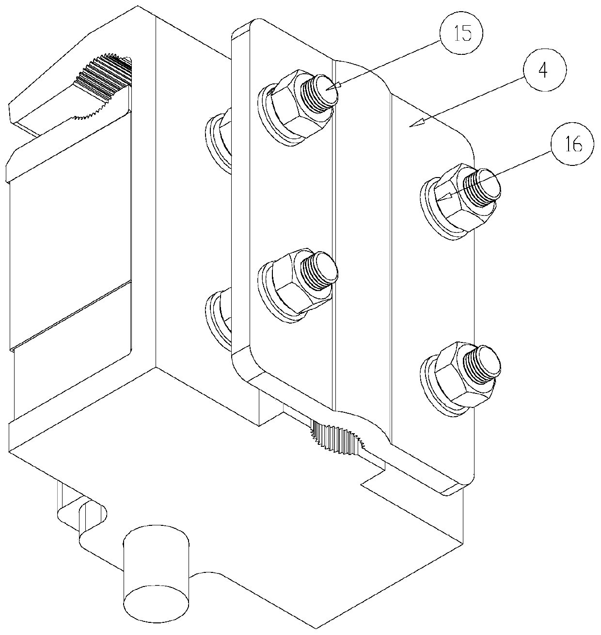
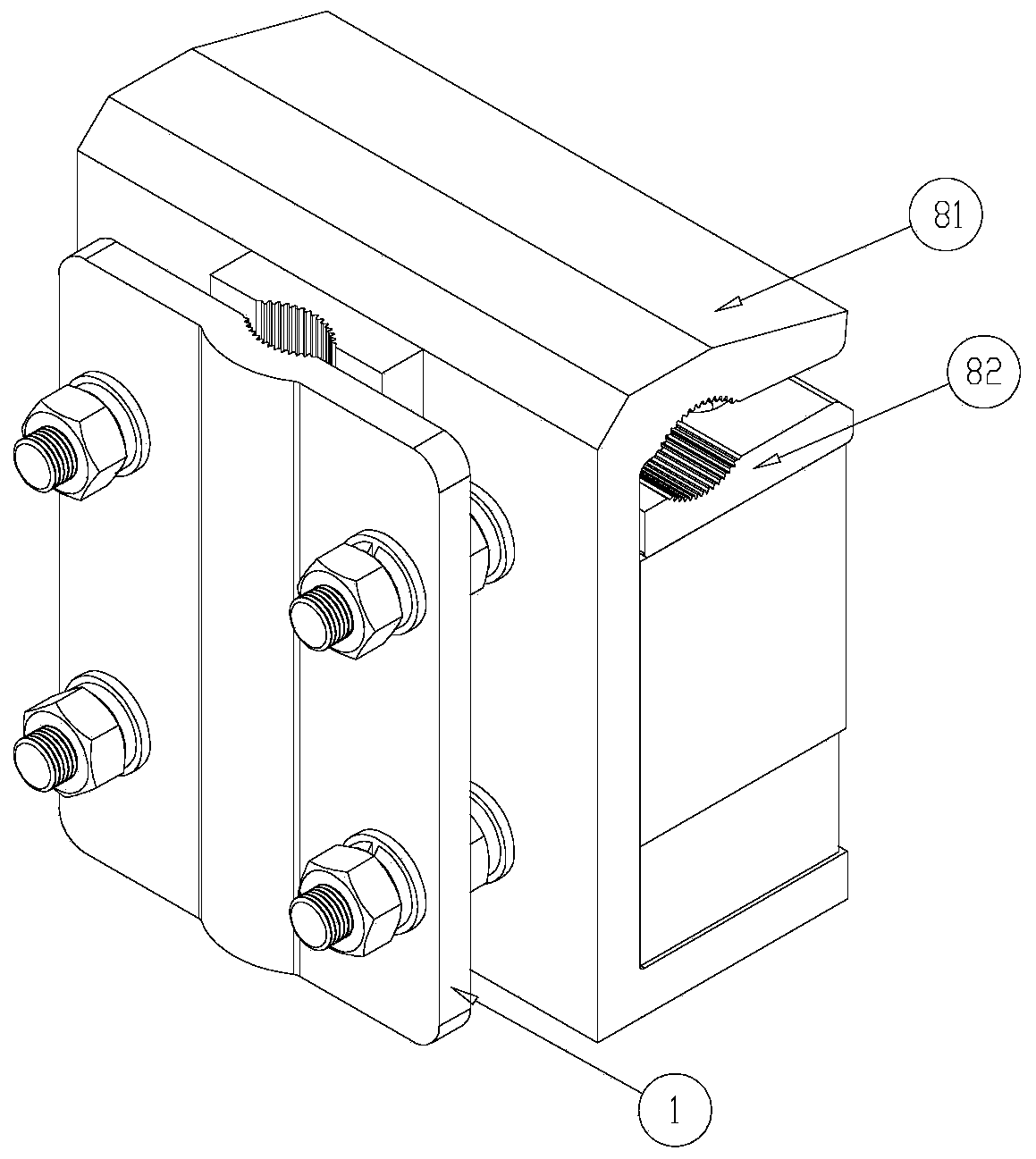
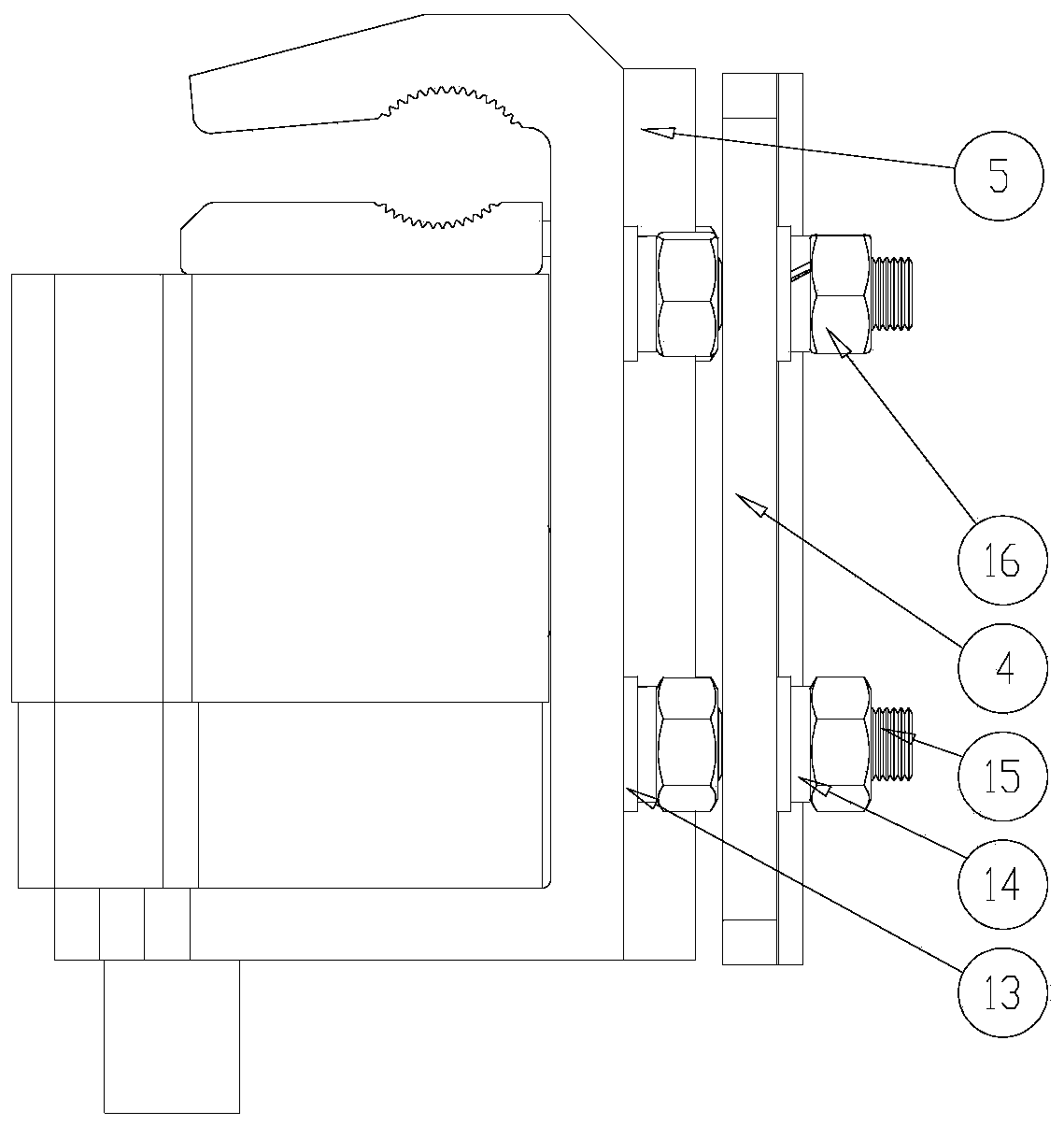
The invention provides a power distribution network ground potential live line connection T wiring device, which comprises a wiring clamp body, a fixed clamping block, a movable clamping block, a fixed clamping plate, a movable clamping plate, a lifting assembly and an insulating worm and gear assembly. The fixed clamping block is arranged on the wiring clamp body and extends along the horizontaldirection together with the movable clamping block. The fixed clamping block and the movable clamping block are oppositely arranged and form a first wire clamping space. The fixed clamping plate is arranged on the wiring clamp body and extends along the vertical direction together with the movable clamping plate. The fixed clamping plate and the movable clamping plate are oppositely arranged and form a second wire clamping space. The first wire clamping space is located on one side of the wiring clamp body, and the second wire clamping space is located on the other side of the wiring clamp body. The lifting assembly is connected to the lower surface of the movable clamping block. The worm and gear assembly is used for driving the movable clamping block to ascend and descend. The T-shaped wiring clamp can realize live line connection in a live state, and can prevent power failure caused by live line connection from influencing normal power supply to users.

Description

technical field [0001] The invention relates to the technical field of electric power bonding, in particular to a T-connection device for ground potential live bonding of a power distribution network. Background technique [0002] In a high-voltage power system, when a new line or a new user transformer needs to be connected to the power network and put into operation, the live wire device generally used in the current power distribution line is a copper-aluminum parallel groove clamp, which is a kind of It is a device used in 35kV and 10kV distribution network line lapping and T-connection. At present, new 10kV new lines and new users need to be used for power outages and ditch line clips T-connection and fire-fighting, and power-off fire-bonding needs to be in accordance with the requirements of the power industry. Applying in advance, the application period is long, and power outages need to be planned as a whole, which greatly reduces the convenience for new users to use...

Claims


Application Information

Patent Timeline
Patent Type & Authority Applications(China)
IPC IPC(8): H01R11/05H01R11/01H01R4/28H01R4/46H01R43/027
CPCH01R4/28H01R4/46H01R11/01H01R11/05H01R43/027
Inventor 唐晚成王庆红杨永祥王颖李广凯林龙钱安顺李晓涂达胜勾清亮吴恩宇王静萍王亚萍艾谵罗欢瞿洪江陈明举蒋递荣瞿灿何孟赵庆军杜飞
Owner GUIZHOU POWER GRID CO LTD
Learn More