Waste gas collecting and processing device, and workpiece cleaning system

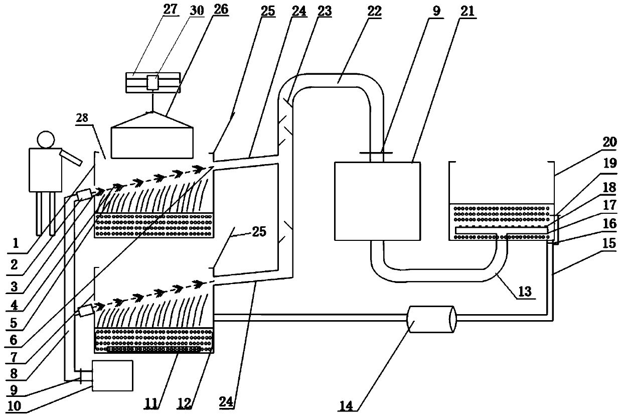
A treatment device and waste gas collection technology, which are applied in the fields of removing smoke and dust, cleaning methods and utensils, and separation of dispersed particles. It can solve problems such as unfavorable safety operations, burn operators, and complex acid mist treatment processes, achieve a safe operating environment, improve Efficiency, the effect of preventing high temperature gas burns and exhaust gas hazards

Pending Publication Date: 2020-01-24
JIANGSU XCMG CONSTR MASCH RES INST LTD
View PDF0 Cites 2 Cited by
  • Summary
  • Abstract
  • Description
  • Claims
  • Application Information

AI Technical Summary

Problems solved by technology

[0003] The workpiece after high-temperature cleaning needs to be rinsed to remove surface residues. Due to the high temperature of the workpiece, a large amount of high-temperature water vapor will be generated when the workpiece is placed in the rinse tank. On the one hand, there is a risk of scalding the operator, and on the other hand, it will speed up the workshop. Corrosion of equipment such as driving and transportation mechanisms poses potential safety hazards
[0004] After rinsing, the workpiece needs to be cleaned by ultrasonic derusting to remove oxide skin, rust and other defects on the surface. However, most of the existing ultrasonic derusting cleaning solutions are acidic media. Since there is no suitable protection and collection device during the cleaning process, acid mist is likely to be generated. Diffuse, causing environmental pollution, affecting the health of operators and equipment reliability, which is not conducive to safe operation, and the acid mist treatment process is complicated and the equipment cost is high

Method used


Image

  • Waste gas collecting and processing device, and workpiece cleaning system
  • Waste gas collecting and processing device, and workpiece cleaning system

Examples


Embodiment Construction

[0054]The present invention will be described in detail below. In the following paragraphs, different aspects of the embodiments are defined in more detail. Aspects so defined may be combined with any other aspect or aspects unless specifically stated otherwise. In particular, any feature considered to be preferred or advantageous may be combined with one or more other features considered to be preferred or advantageous for heavy-duty machinery.

[0055] Terms such as "first" and "second" appearing in the present invention are only for convenience of description, to distinguish different components with the same name, and do not indicate a sequence or a primary and secondary relationship.

[0056] In addition, when an element is referred to as being "on" another element, the element may be directly on the other element or may be indirectly on the another element with an interposed therebetween. More intermediate elements. Also, when an element is referred to as being "conne...


PUM


Abstract

The invention provides a waste gas collecting and processing device, and a workpiece cleaning system. The waste gas collecting and processing device comprises an accommodating groove (1; 7) configuredto contain a cleaning fluid; an air blowing opening (3) is formed in a first side wall of the accommodating groove (1, 7), an air suction opening (6) is formed in a second side wall of the cleaning tank (1, 7), the first side wall and the second side wall are oppositely arranged, and the air blowing opening (3) and the air suction opening (6) are higher than cleaning liquid; an air blowing component (10) and an air suction component (21) are respectively communicated with the air blowing port (3) and the air suction port (6); and an air curtain layer (4) is formed in an area between the air blowing port (3) and the air suction port (6) in the accommodating grooves (1; 7) in a state that the air blowing component (10) and the air suction component (21) are turned on. According to the wastegas collecting and processing device, waste gas in a tank body can be prevented from escaping, environment-friendly treatment of the waste gas can be achieved, and the automatic cleaning efficiency is improved; and moreover, a pollution-free and safe operation environment is provided for operators.

Description

technical field [0001] The invention relates to the technical field of exhaust gas treatment, in particular to an exhaust gas collection and treatment device and a workpiece cleaning system. Background technique [0002] Paint, oil, and rust on the surface of construction machinery parts need to undergo high-temperature cleaning, residue rinsing, ultrasonic derusting, residual liquid rinsing, and fine cleaning in order to ensure the surface quality of parts and meet different production needs such as processing, painting, and assembly. , how to realize the collection and treatment of waste gas in a safe, efficient and environmentally friendly manner is the key to the cleaning process. [0003] The workpiece after high-temperature cleaning needs to be rinsed to remove surface residues. Due to the high temperature of the workpiece, a large amount of high-temperature water vapor will be generated when the workpiece is placed in the rinse tank. On the one hand, there is a risk o...

Claims


Application Information

Patent Timeline
Patent Type & Authority Applications(China)
IPC IPC(8): B01D53/40B01D53/42B01D53/78B08B15/04
CPCB01D53/40B01D53/42B01D53/78B08B15/04
Inventor 陈善功蹤雪梅王光存
Owner JIANGSU XCMG CONSTR MASCH RES INST LTD
Why Eureka
Try Eureka