
Aero-engine fuel nozzle structure

An aero-engine and fuel nozzle technology, applied in the combustion chamber, combustion method, combustion equipment and other directions, can solve the problems affecting combustion stability, nozzle strength and life risk, oil circuit instability, etc., to avoid fuel coking and reduce fuel consumption. The risk of coking and the effect of reducing the heat transfer area

Active Publication Date: 2020-01-24
AECC COMML AIRCRAFT ENGINE CO LTD
View PDF8 Cites 9 Cited by
  • Summary
  • Abstract
  • Description
  • Claims
  • Application Information

AI Technical Summary

Problems solved by technology

[0007] With the improvement of the comprehensive performance requirements of aero-engines, it will inevitably lead to higher temperature rise and higher pressure of the airflow in the combustion chamber. At the same time, the nozzle generates large vibrations, which will lead to oil circuit instability, further affect the stability of combustion, and bring greater challenges to the life and reliability of fuel nozzles

Method used


Image

  • Aero-engine fuel nozzle structure
  • Aero-engine fuel nozzle structure
  • Aero-engine fuel nozzle structure

Examples


Embodiment Construction

[0052] A variety of different implementations or examples for implementing the described subject technical solutions are disclosed below. In order to simplify the disclosure, the following describes the specific examples of each component and arrangement, of course, these are only examples, not limiting the protection scope of the present invention. For example, the description that the first feature described later in the description is formed on or above the second feature may include an embodiment in which the first and second features are formed through direct contact, and may also include an embodiment in which the first and second features are formed between the first and second features. Embodiments of additional features such that there may be no direct relationship between the first and second features. Additionally, reference numerals and / or letters may be repeated in different instances in these disclosures. This repetition is for brevity and clarity and does not i...


PUM


Abstract

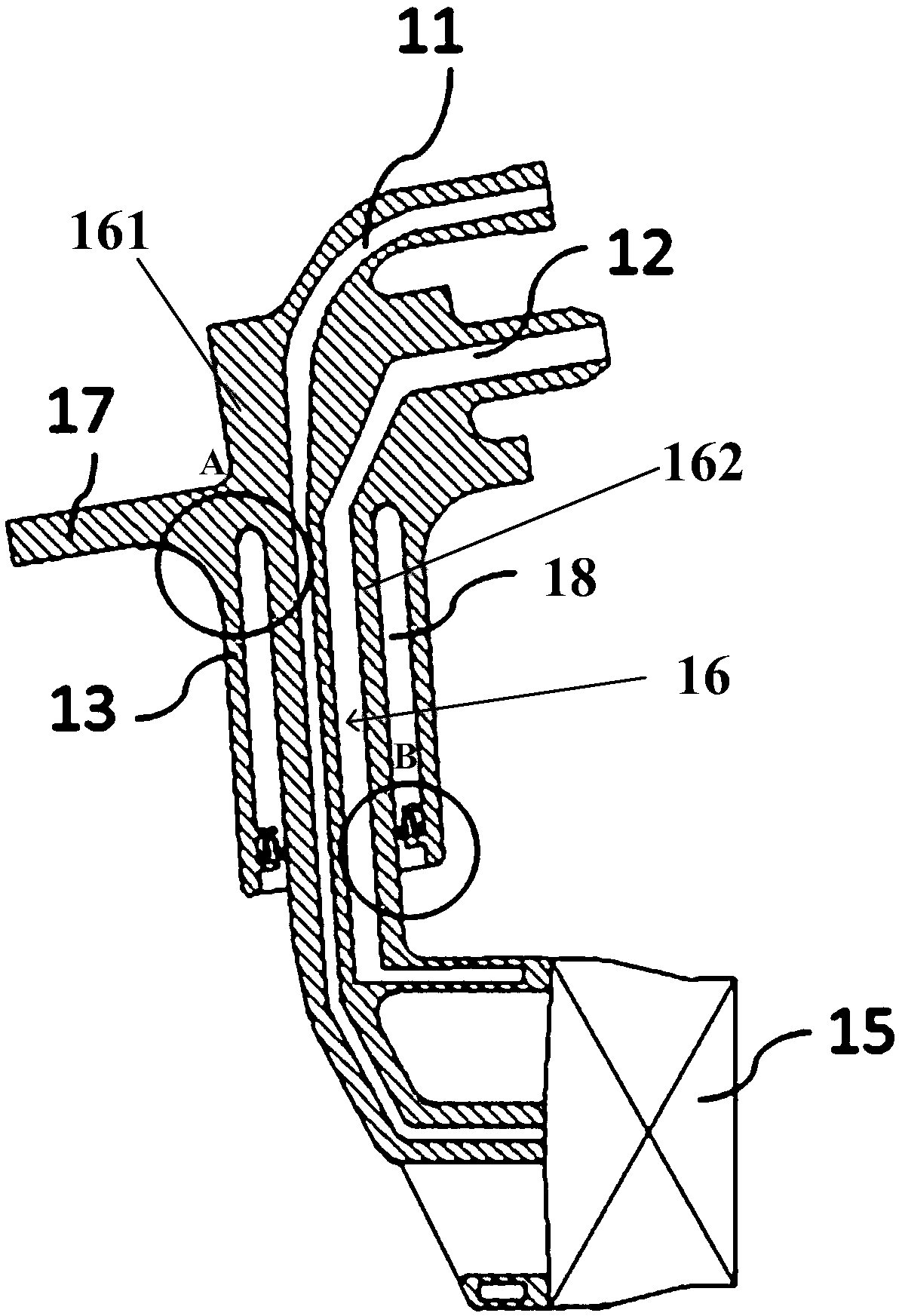
The invention discloses an aero-engine fuel nozzle structure. The fuel nozzle structure comprises a sleeve shell and an oil conveying part, wherein the oil conveying part comprises a first oil conveying part and a second oil conveying part, one end of the second oil conveying part is integrally connected with the first oil conveying part, and the other end of the second oil conveying part is connected with an auxiliary vortex device, the sleeve shell is integrally formed with the oil conveying part, a sleeve is arranged outside the second oil conveying part and is extended to the second oil conveying part from the boundary of the first oil conveying part and the second oil conveying part, a semi-closed air heat insulation cavity is provided with the radial space between the second oil conveying part and the sleeve, and elastic pieces which are in contact with the opposite side walls of the air heat insulation cavity are arranged on the open side of the air heat insulation cavity. The fuel nozzle structure has the advantages of stable and reliable structure, long service life and the like.

Description

technical field [0001] The invention belongs to the technical field of aero-engines, in particular to a fuel nozzle structure for aero-engines. Background technique [0002] The fuel nozzle is one of the key components of the aero-engine combustion chamber. In the annular combustion chamber, the fuel nozzles are evenly distributed on the positioning device of the flame tube head, and are fixed on the combustion chamber casing by bolts of the nozzle mounting plate. The fuel enters the oil delivery part of the nozzle through the external pipeline, and then enters the flame tube of the combustion chamber through swirl atomization to participate in combustion. The fuel nozzle is placed at the outlet of the compressor, and the outlet temperature of the compressor is about 500-1000K. Under the high-temperature air flow, the nozzle bears a large heat load, which will not only cause the oil temperature in the oil delivery part of the nozzle to rise and cause coking and clogging, but...

Claims


Application Information

Patent Timeline
Patent Type & Authority Applications(China)
IPC IPC(8): F23R3/28
CPCF23R3/28
Inventor 杨眉杨玫
Owner AECC COMML AIRCRAFT ENGINE CO LTD
Learn More