Electricity thick liquid torch trigger device

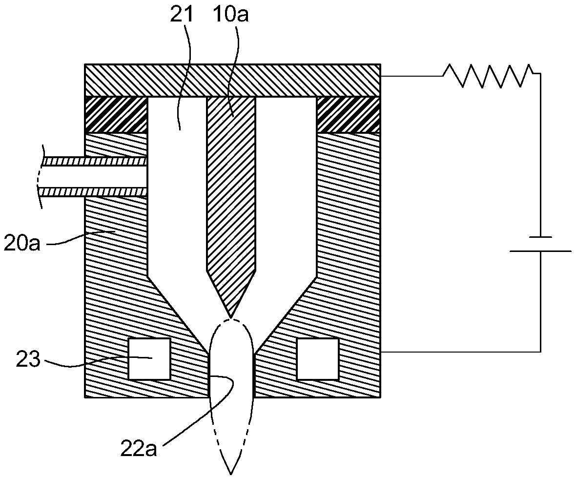
A technology of plasma and ionization, applied in the field of plasma torch, can solve the problems affecting the service life of the pole core 20a, unsatisfactory structural design, etc., and achieve the effect of increasing the flame temperature and flame length

Inactive Publication Date: 2020-01-24
ORIENT SERVICE
View PDF10 Cites 0 Cited by
  • Summary
  • Abstract
  • Description
  • Claims
  • Application Information

AI Technical Summary

Problems solved by technology

However, the structural design of the existing pole core 20a for water circulation and heat exchange is not ideal, which is also one of the reasons for affecting the service life of the pole core 20a

Method used


Image

  • Electricity thick liquid torch trigger device
  • Electricity thick liquid torch trigger device
  • Electricity thick liquid torch trigger device

Examples


Embodiment Construction

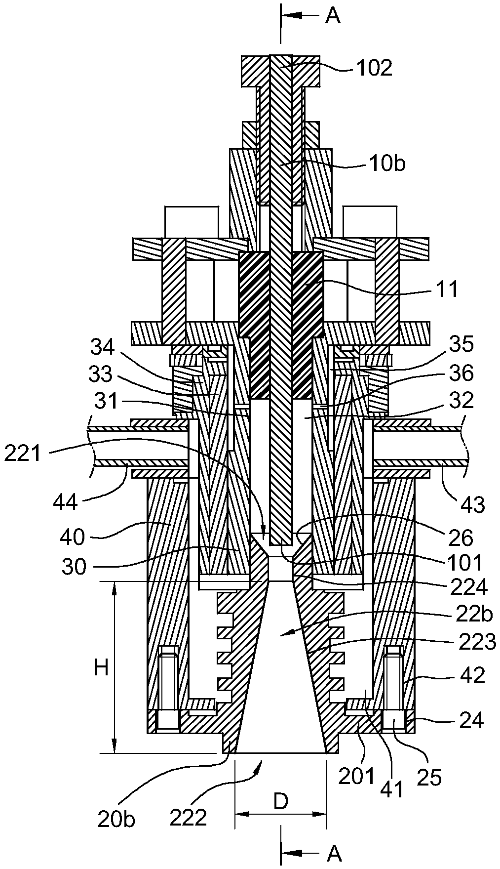
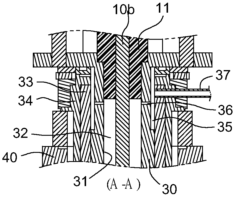
[0021] First, please incorporate the figure 2 and image 3 , discloses a preferred embodiment of a plasma torch excitation device provided by the present invention, and illustrates that the plasma torch excitation device includes a pole core frame 30, a pole rod 10b and a pole core 20b, wherein:

[0022] The pole core frame 30 is roughly made into a seat tube shape, so that the pole core frame 30 has a hollow chamber 31 . In practice, the pole 10b is made of conductive metal into a bar shape, so that the pole 10b has an ion projecting end 101 and an electric connection end 102, and the pole 10b is fixed by being held in the middle by an insulating sleeve 11 On the pole core frame 30, and the ion projecting end 101 of the pole rod 10b can be implanted in the chamber 31, thereby forming a gas collection groove 32 surrounding the pole rod 10b and the surrounding walls of the chamber 31, And the power-connecting end 102 of the pole rod 10b protrudes out of the core frame 30 to ...


PUM


Abstract

The invention provides an electricity thick liquid torch trigger device, has a cabin including a pole piece frame, this cabin interplantation goes into one and extremely excellent and form one aroundthe gas collecting groove in between the extremely excellent and cabin wall, a pole piece has been put admittedly to the bottom of this pole piece frame, this pole piece has a core hole, inner this gas collecting groove of intercommunication in this core hole, the bocca of torch is starched to the outer end in this core hole as the electricity, wherein should extremely excellently have an electricion throws the end, this electric ion throws the end and is close to in the inner in this core hole, it is a conical hole wall to form between the inner in this core hole and the outer end, thisconical hole wall is expanded gradually to this outer end and is formed by this the inner, so, improve tradition electricity thick liquid torch because of the narrow and shallow limited problem of flame temperature and flame length that causes in core hole.

Description

technical field [0001] The invention relates to a plasma torch (Plasma torch) generated by exciting electric ions from electrodes, in particular to a plasma torch excitation device. Background technique [0002] Plasma torch is a high-temperature flame that can generate a directional plasma jet. The temperature of plasma torch can be as high as 3000℃~10000℃, so it is commonly used in material processing, welding, waste treatment, ceramic cutting , metal cutting and semiconductor waste gas sintering and other purposes. [0003] see figure 1 , which discloses the generation technology of the existing plasma torch, including the use of DC, AC or DC with tens of volts (V) and hundreds of amperes (A) between the pole rod 10a of an anode and the pole core 20a of a cathode. RF power supply, and a gas collection tank 21 is formed between the pole rod 10a and the pole core 20a, and in the gas collection tank 21, for example, He, Ar, N2 or O2 are introduced into the gas collection t...

Claims


Application Information

Patent Timeline
Patent Type & Authority Applications(China)
IPC IPC(8): H05H1/22
CPCH05H1/22H05H1/34H05H1/3484H05H1/38H05H1/28H05H1/3478
Inventor 冯五裕
Owner ORIENT SERVICE
Why Eureka
Try Eureka