Glass melting furnace and method for melting glasses

a glass melting furnace and glass technology, applied in glass furnaces, glass making apparatus, furnace types, etc., can solve the problems of unavoidable creation of oxides of nitrogen, poor heat transfer, and risk of vaporization of volatile glass components, so as to reduce flow velocity, improve heat transfer rate, and increase oxygen content

Inactive Publication Date: 2010-07-15
BETEILIGUNGEN SORG
View PDF12 Cites 8 Cited by
  • Summary
  • Abstract
  • Description
  • Claims
  • Application Information

AI Technical Summary

Benefits of technology

[0012]The object of the invention is therefore to provide a glass melting furnace and operating method in which the partially contrary causes and effects are unified without the use of an external heat exchanger, so that the batch components do not start to melt or stick to one another or to the surfaces of the heat exchanger, and segregation does not take place, while at the same time complying as far as possible with regulations concerning environmental pollution and energy wastage. The intention is also to achieve a reduction in the entrainment of certain batch components in the waste gases and in the dust content of the waste gases, which can also influence the glass quality. Furthermore, it is intended to utilise primary measures in the melting installation to reduce the emissions of nitrogen oxides, without detriment to the efficiency and without the necessity of providing additional operating systems, equipment or personnel.
[0018]The object of the invention is therefore completely achieved by a glass melting furnace and operating method in which the partially contrary causes and effects are unified without the use of an external heat exchanger, so that the batch components do not start to melt or stick to one another or to the surfaces of the heat exchanger, and segregation does not take place, while at the same time complying as far as possible with regulations concerning environmental pollution and energy wastage. In addition there is a reduction in the entrainment of certain batch components and in the dust content of the waste gases, so that the influence on the glass quality is reduced. Furthermore, primary measures in the melting installation are used to reduce the emissions of nitrogen oxides, without detriment to the efficiency and without the necessity of providing additional operating systems, equipment or personnel. In particular, the specific energy consumption, based on a tonne of melted glass, is significantly reduced by the invention.
[0038]The effect of the double heating of the charging material from above and below is explained as follows: On the one hand the combustion with an oxidation gas with an increased oxygen content compared with air produces higher flame temperatures, while on the other hand, the specific waste gas quantities and, if the combustion chamber dimensions remain unchanged, the flow velocities are reduced. This leads to the situation in which the heat transfer in the region of the combustion, or in other words the radiating flames, is relatively high whereas in those areas away from the flames, and here in the batch charging area, a lower rate of heat transfer is found. This is the reason for the proposals already known—for example in U.S. Pat. No. 5,807,418—which suggest the use of external heat exchangers to preheat charging material and gases. The subject of this invention goes in a different and more advantageous direction involving the use of bubblers and bubbler gases. The bubbler gas produces a strong rising current in the glass bath above each entry location, whereby the return current that moves below the charging material towards the charging end of the furnace is strengthened and the melting effect from below is increased. At the same time during its rise the bubbler gas is raised more or less to the temperature of the glass melt, which is normally at its highest at this location. Then, the bubbler gas is pulled into and mixed with the combustion gases, such that the gas quantity and the flow velocity of this mixture over the charging material in the direction of the charging end of the furnace are increased, as is the melting effect from above. This extremely efficient heat transfer takes place entirely within the furnace and therefore over a short distance, and therefore improves the heat balance, reduces the building, operating and maintenance costs and decreases the susceptibility to disturbance of the complete glass melting unit. The low concentration of nitrogen oxides is retained.

Problems solved by technology

This document contains a detailed description of the diametrically opposed problems that occur when glass is melted, such as poor heat transfer as a result of the poor thermal conductivity of the charging material and the glass melt, the difficult homogenization of the melt caused by its high viscosity, the risk of vaporization of volatile glass components as a result of long residence times on the flow paths, the unavoidable creation of oxides of nitrogen during the combustion of fossil fuels, and the reduction of the quantity of these oxides by increasing the oxygen content in the oxidation gas, the need for high temperatures in the furnace superstructure, the glass melt and the combustion gases, the resulting thermal and chemical stress on the mineral materials used in the furnace construction, and environmental pollution caused by pollutants in the waste gases, in particular from combinations of nitrogen and oxygen.
The total furnace surface area is also a source of energy costs, either as a result of heat conduction or radiation or the cooling of critical components, whereby these costs vary according to the furnace size.
However, legal requirements concerning the specific energy consumption and environmental pollution resulting from both energy consumption and waste gases have been drastically tightened, both for the energy suppliers and the furnace operation itself, so that the complex relationships mentioned above must be reconsidered.
Adding air to the fuel results in a high flame temperature.
This is one of the main causes of the formation of pollutant nitrogen oxides.
However, this technology has disadvantages; not only is a heat exchanger required for the heat transfer to the combustion air, but the furnace must be very long and deep, and the design of the superstructure and crown is complicated.
The complex construction over the complete furnace length and the large surface area result in significantly higher heat losses to the environment that cannot be reduced by very much by the use of normal thermal insulation.
Therefore the investment and operating costs for the complete installation are high.
Another disadvantage of this solution is that the economics are not improved.
However the reduction achieved is not sufficient to compensate for the additional cost of oxygen production.
Therefore the operating costs are still higher than those of an installation with gas-air heating and regenerative heat recovery.
External heat exchangers are expensive auxiliary items that require a great deal of maintenance, and also produce further heat losses, as there is no thermal insulation that can completely eliminate heat loss.
In addition certain batch components may start to melt during this preheating, and stick to the surfaces of the heat exchanger, and when there is direct contact between the waste gases and the batch, not only do some components begin to melt, but segregation may occur and certain batch components can also be picked-up by the gases, and so the dust content of the waste gases may exceed permissible limits, or expensive dust filters must be installed in order to prevent this happening.
The risk of sticking is also increased by water in the charging material that turns to steam, or water present in the combustion gases.
However, in the summary it is stated clearly that when batch preheating is used there is also the risk of segregation, which can lead to a change in the batch composition.
As there is no insulating material that allows no heat to pass through the additional pipework and the large volume heat exchanger it must result in an increase in the fuel consumption and heat losses to the environment, whereby a premature draw-off of combustion gases is equivalent to a source of losses for the combustion chamber.

Method used


Image

  • Glass melting furnace and method for melting glasses
  • Glass melting furnace and method for melting glasses

Examples


Embodiment Construction

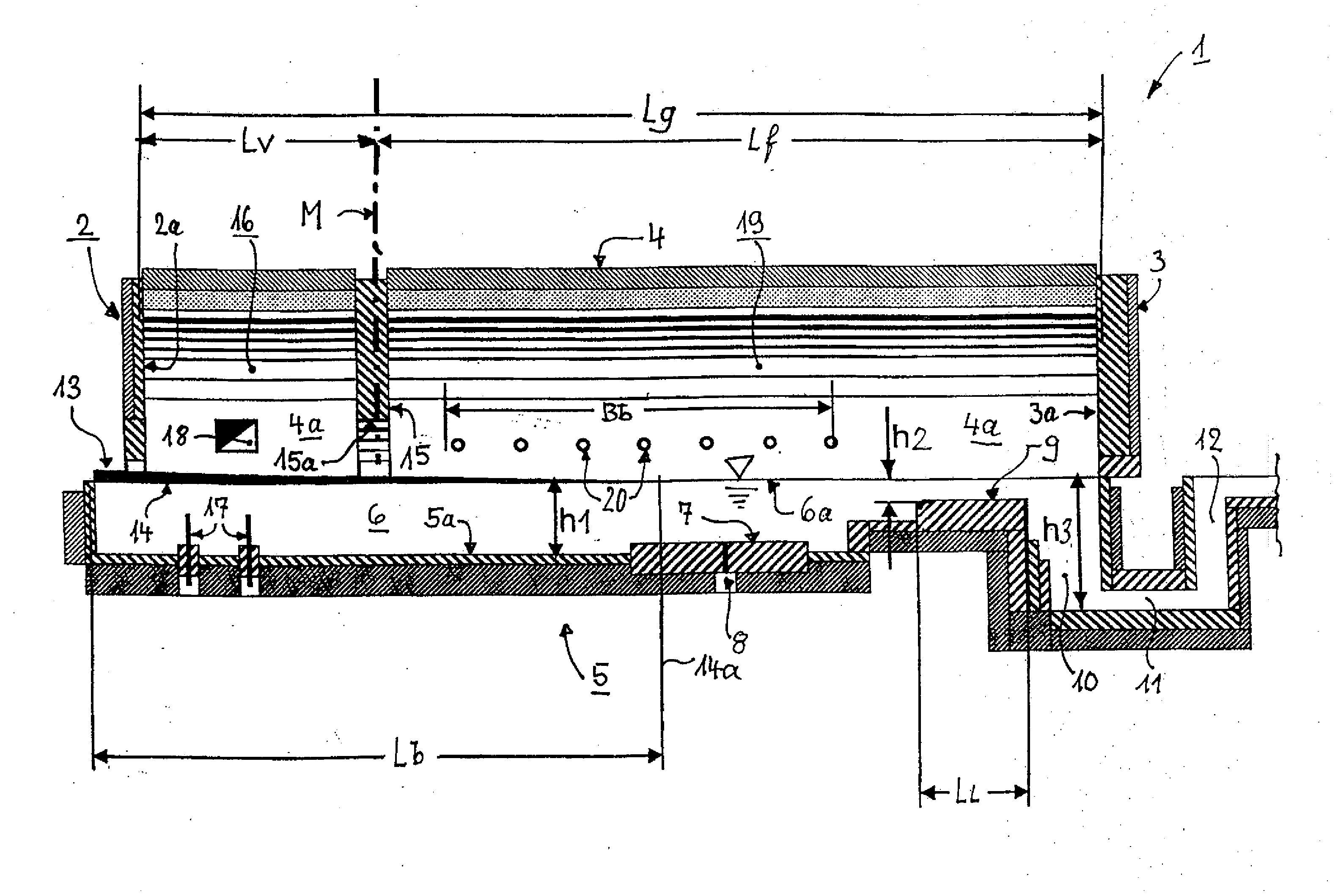
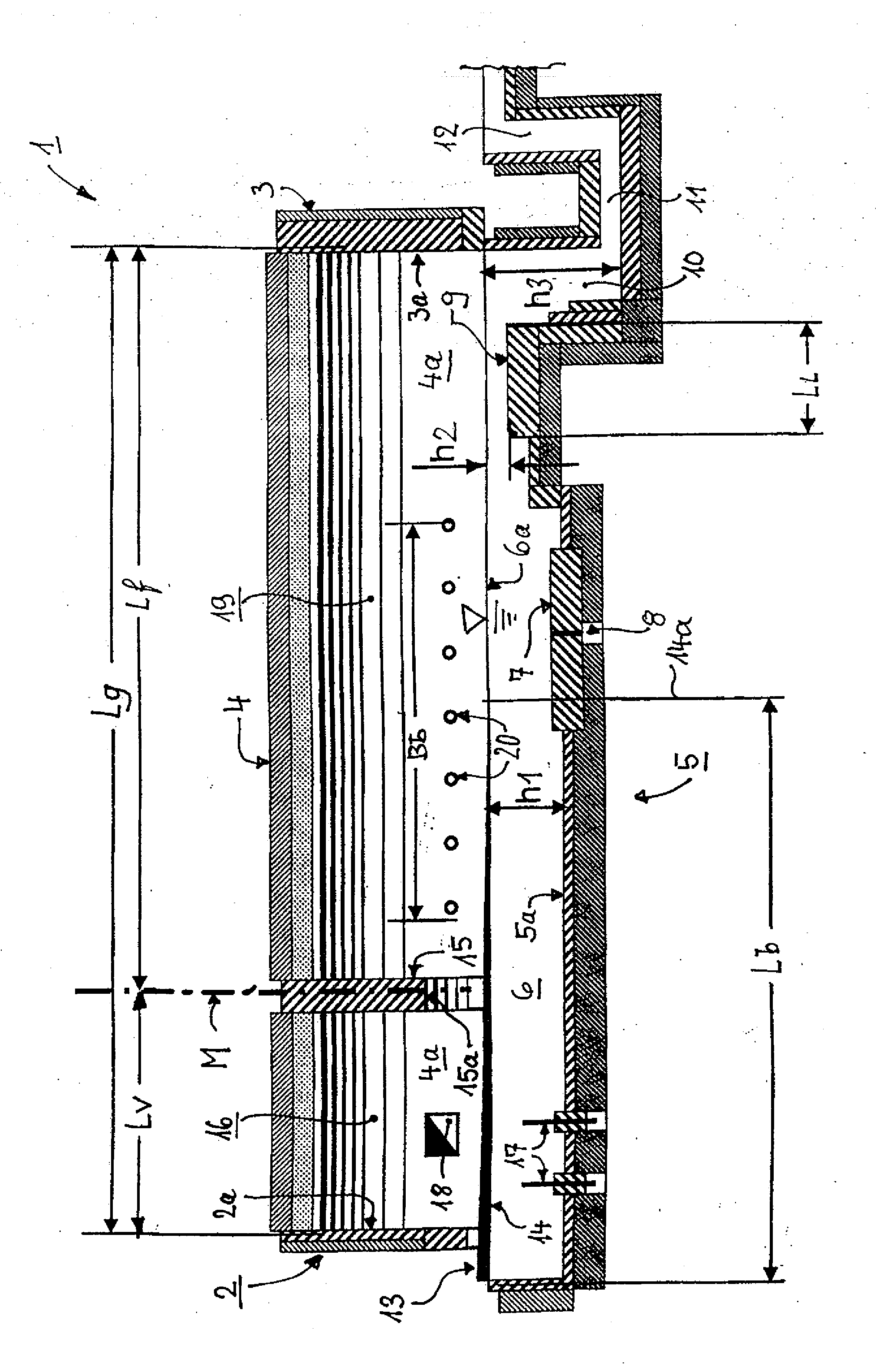
[0040]At the charging end of a superstructure 1 there is a first end wall 2 and at the extraction end there is a second end wall 3, and an arched furnace crown 4 extends between these two walls. The furnace crown 4 merges on both sides into vertical side walls 4a, of which only the rear wall is visible here. Below the superstructure 1 there is a tank 5, which is designed to hold and process a glass melt 6, the surface of which is indicated at location 6a. The tank 5 has a tank bottom 5a, from which a retaining plate 7 with a row of bubblers 8 protrudes upwards. Thereafter the tank bottom 5a is stepped up to the raised part of the bottom 9, and after this raised part of the bottom 9 there follows a homogenization zone 10, a bottom outlet 11 and a vertical channel 12.

[0041]A charging opening 13 is located below the bottom edge of the end wall 2 and above the melt surface 6a and this charging opening 13 can extend across the complete width of the tank 5. The charging material 14, intro...


PUM

PropertyMeasurementUnit
sizeaaaaaaaaaa
sizeaaaaaaaaaa
internal widthaaaaaaaaaa

Abstract

A glass melting furnace with a tank and a superstructure with a furnace crown and a total internal length (“Lg”), with a preheating zone for charging material and a combustion zone with burners. A single radiation wall is located between the preheating zone and the combustion zone such that the length of the preheating zone is between 15 and 35% of the total internal length and the length of the combustion zone is between 65 and 85% of the total internal length. The preheating zone is designed for use solely with preheating of the charging material within the furnace. The oxidation gas supply contains at least 85 volume percent oxygen and at least one outlet for the waste gases from the preheating zone is connected to the atmosphere without a heat exchanger.

Description

BACKGROUND OF THE INVENTION[0001]The invention relates to a glass melting furnace for melting glasses, in particular glasses from the group of soda-lime glasses, in particular container glass, or flat glass for rolling processes, and technical glasses, in particular borosilicate glass or neutral glass, having a tank and a furnace superstructure with a furnace crown and a total internal length (“Lg”), that together have a preheating zone for charging material with at least one outlet for waste gases, a combustion zone with burners, a raised part of the bottom, an homogenization zone, a bottom outlet and a vertical channel for the glass melt, whereby, the burners, in addition to a connection for fossil fuel, are equipped with a connection for a gas supply for oxygen-rich oxidizing gas, and whereby at least one row of bubblers is installed in the combustion zone in front of the raised part of the bottom.[0002]The nearest state-of-the-art is considered to be contained in European patent...

Claims


Application Information

Patent Timeline
Patent Type & Authority Applications(United States)
IPC IPC(8): C03B5/18C03B5/16
CPCC03B5/04C03B5/185C03B5/2353C03B5/2257C03B5/193C03B5/20Y02P40/50
Inventor SORG, HELMUT
Owner BETEILIGUNGEN SORG
Why Eureka
Try Eureka