Energy recovery system of railway vehicle
A rail vehicle and energy recovery technology, applied in the field of rail transportation, can solve the problems of increasing the total weight of rail vehicles, affecting the energy consumption of rail vehicles, increasing costs, etc., to achieve the goal of reducing operating costs, prolonging service life, and reducing wear Effect
- Summary
- Abstract
- Description
- Claims
- Application Information
AI Technical Summary
Problems solved by technology
Method used
Image

Examples
Embodiment 1
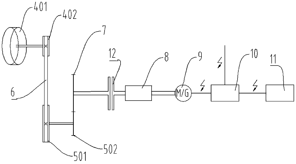
[0039] Such as Figure 1 to Figure 6 As shown, the present invention provides a rail vehicle energy recovery system, including a generator 9, a conversion circuit 10, a battery pack 11, a friction strip 3, a swing arm 13, a first rotating assembly 4, a hydraulic cylinder 14, and a second rotating assembly 5 , auxiliary gear 7 and controller; wherein, generator 9, conversion circuit 10, battery pack 11, swing arm 13, first rotating assembly 4, hydraulic cylinder 14, second rotating assembly 5, auxiliary gear 7 and controller are all set In a station, not necessarily inside a vehicle. As a preference, the controller can use Siemens S7-1200;
[0040] The generator 9 is connected to the storage battery pack 11 through the conversion circuit 10 , and the electric energy output by the generator 9 is stored in the storage battery pack 11 through the conversion circuit 10 .
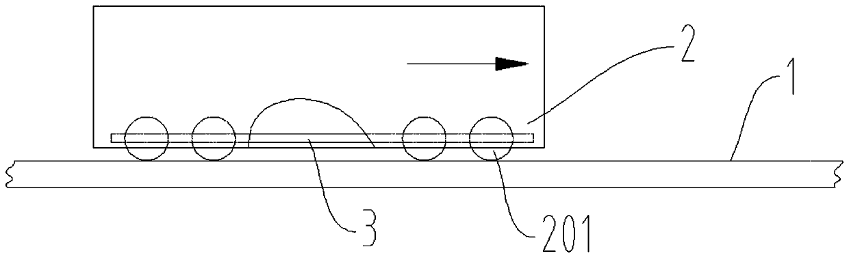
[0041] The friction strip 3 is installed on the girder of the carriage 2 in the rail vehicle, and is located...
Embodiment 2
[0056] Such as figure 1 , figure 2 , image 3 with Figure 4 As shown, a rail vehicle energy recovery system includes a generator 9, a conversion circuit 10, a battery pack 11, a friction strip 3, a swing arm 13, a first rotating assembly 4, a hydraulic cylinder 14, a second rotating assembly 5, and auxiliary gears 7 and the controller; the generator 9 is connected to the battery pack 11 through the conversion circuit 10; wherein, the generator 9, the conversion circuit 10, the battery pack 11, the swing arm 13, the first rotating assembly 4, the hydraulic cylinder 14, the second The rotating assembly 5, the auxiliary gear 7 and the controller are all located in the station, not necessarily inside the vehicle.
[0057] The friction strip 3 is installed on the girder of the carriage 2 in the rail vehicle, and is located at the lower part of the carriage 2;
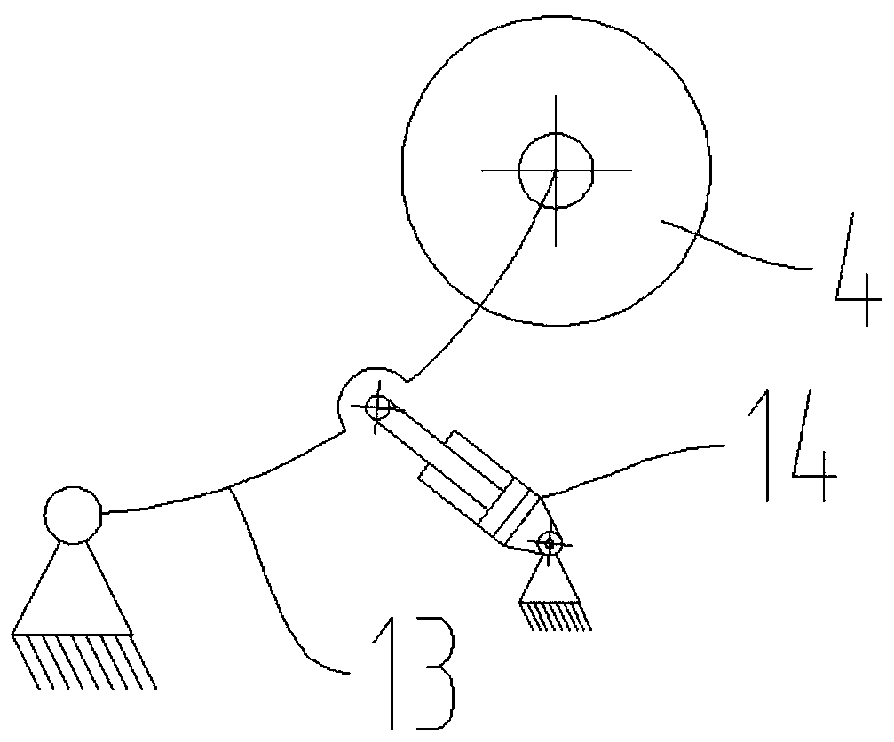
[0058] The swing arm 13 is positioned at the inner side of the running track 1 of the rail vehicle, and one end of t...
PUM
 Abstract
Description
Claims
Application Information
 - R&D Engineer
- R&D Manager
- IP Professional
- Industry Leading Data Capabilities
- Powerful AI technology
- Patent DNA Extraction
Browse by: Latest US Patents, China's latest patents, Technical Efficacy Thesaurus, Application Domain, Technology Topic.
© 2024 PatSnap. All rights reserved.Legal|Privacy policy|Modern Slavery Act Transparency Statement|Sitemap