A low-floor tram floating car end beam and lower hinged mounting seat structure

A technology for trams and mounting seats, which is applied to railway car body parts, railway car bodies, transportation and packaging, etc., and can solve cracks at the end of the car body and hinged seats, large force on the mounting seat and end beam, and force on the hinged mechanism Large and other problems, to achieve the effect of reducing self-weight, reasonable force, and consistent transmission path

Active Publication Date: 2020-09-01
中铁轨道交通装备有限公司
View PDF5 Cites 0 Cited by
  • Summary
  • Abstract
  • Description
  • Claims
  • Application Information

AI Technical Summary

Problems solved by technology

[0003] However, in the current low-floor trams, the end beam of the base machine for the installation of the hinge mechanism bears the complex dynamic load of the hinge mechanism, and the force of the hinge mechanism is large, and there is no buffer energy-absorbing device, and the force is directly transmitted to the installation of the hinge mechanism. on the seat and end beam, resulting in a large force on the hinge mechanism mounting seat and end beam
If the design of the mounting seat and end beam is unreasonable, there will be safety hazards that may cause cracks at the end of the car body and the hinged seat until they are destroyed. Therefore, strong bearing capacity of the mounting seat and end beam is a condition that must be met

Method used


Image

  • A low-floor tram floating car end beam and lower hinged mounting seat structure
  • A low-floor tram floating car end beam and lower hinged mounting seat structure
  • A low-floor tram floating car end beam and lower hinged mounting seat structure

Examples


Embodiment Construction

[0023]The present invention will be described in detail below in conjunction with the accompanying drawings and specific embodiments.

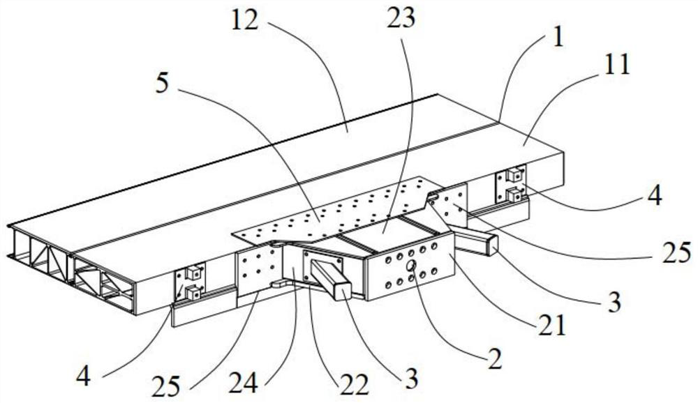
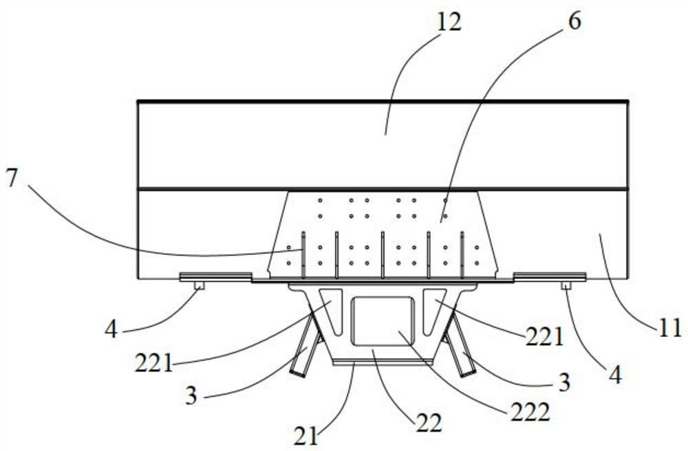
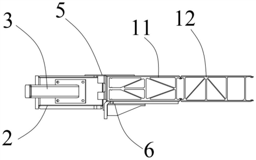
[0024] figure 1 , figure 2 with image 3 In order to solve the above-mentioned technical problems, the present invention is achieved through the following technical solutions: a low-floor tram floating car end beam and lower hinged mounting seat structure, including end beam 1 and the center of the rear end of end beam 1 The hinged mounting base 2, the end beam 1 is respectively provided with a workshop damping mounting base 4 on the left and right sides of the hinged mounting base 2, and the two workshop damping mounting bases 4 are left and right symmetrical with the hinged mounting base 2 as the center , the hinged mounting base 2 is provided with two rotational stoppers 3 that are left and right symmetrical about its center; the end beam 1 is composed of a main profile 11 with a rectangular structure and a secondary profile 12 with a re...


PUM


Abstract

The invention discloses a low-floor tramcar floating car end beam and lower part hinged mounting base structure. The low-floor tramcar floating car end beam and lower part hinged mounting base structure comprises an end beam and a hinged mounted base arranged at the center of the back end of the end beam; two bilaterally symmetrical workshop damping mounting bases are arranged on the end beam; bilaterally symmetrical rotary stops are arranged on the two sides of the hinged mounting base; the end beam is formed by welding a main sectional material and a secondary sectional material front and back; the main sectional material and the secondary sectional material have hollow structures; rib plates capable of improving rigidity and strength are arranged in the main sectional material and the secondary sectional material; the internal part of the hinged mounting base is trapezoidal hollow; and the trapezoidal hollow internal part is provided with a reinforcing rib. The low-floor tramcar floating car end beam and lower part hinged mounting base structure is high in strength performance, simple in structure, convenient to manufacture and maintain and low in cost, and guarantees the lightweight design of the structure on the premise of meeting the bearing capacity; and through the arrangement form of the unique end beam, the hinged mounting base, the rotary stops and the workshop damping mounting bases, the requirement on vehicle operating stability and comfortability is met.

Description

technical field [0001] The invention relates to the field of low-floor trams, in particular to a low-floor tram floating car end beam and a lower hinged mounting seat structure. Background technique [0002] Modern low-floor trams adopt the design scheme of short car body modules in order to meet the requirements of passing through small-radius curves, and the modules are connected by hinge mechanisms. The end beam and the hinged mounting seat need to bear the longitudinal force, lateral force, vertical force and corresponding torsional load generated during the operation of the vehicle, and transmit the above force to another vehicle through the hinge mechanism. At the same time, by constraining and releasing the degree of freedom between the vehicle modules, the vehicle can pass through the small radius curve smoothly and quickly to ensure the smooth running of the vehicle. Therefore, the end beam and the hinged mounting seat are the key components of the low-floor tram. ...

Claims


Application Information

Patent Timeline
Patent Type & Authority Patents(China)
IPC IPC(8): B61F1/00B61F1/10B61D17/20
CPCB61D17/20B61F1/00B61F1/10
Inventor 阚松刘琳峰陈晨王晶晶毕海涛杨坤
Owner 中铁轨道交通装备有限公司
Why Eureka
Try Eureka