Gantry crane combined beam device and installation method

A gantry crane and combined technology, which is applied in the directions of transportation and packaging, load hanging components, supporting structures, etc., can solve the problems of increased difficulty in track installation, high construction costs, and reduced operating efficiency, so as to simplify the construction process and ensure construction Efficiency, the effect of improving construction efficiency

Inactive Publication Date: 2020-11-06
中建八局轨道交通建设有限公司
View PDF4 Cites 0 Cited by
  • Summary
  • Abstract
  • Description
  • Claims
  • Application Information

AI Technical Summary

Problems solved by technology

[0002] During subway shield construction, it is necessary to reserve a shield hoisting port near the tunnel in the station structure for the hoisting of materials and equipment such as shield machines and segments. Due to the large size of the shield machine, the structure at the hoisting shaft needs to be enlarged. About 3m. After the shield machine is hoisted, it is necessary to install a 25T gantry crane to hoist segments and other commonly used materials and tools. The gantry crane foundation is generally selected on the enclosure structure, but the hoisting shaft at the expansion end cannot be installed due to the expansion of the enclosure structure. continuous
[0003] The conventional gantry crane foundation places steel beams on the original concrete support and the roof of the station, but this method cannot remove the concrete support, which affects the hoisting of the shield tunnel and the lowering of materials such as the hoisting segment of the gantry crane in the later stage, and cannot be used in the hoisting of the shield tunnel and the excavation process. In this method, during the shield construction process, the concrete support bottom needs to be provided with a column and supported on the top of the station. During the shield construction period, the enlarged end top plate is not constructed, so the column cannot be installed and is not operable.
[0004] The enlarged end gantry crane foundation adopts reinforced concrete beams at the enlarged end of the shield hoisting shaft, and the construction starts after the shield machine hoisting is completed. Due to the large span, the reinforcement and cross-section of the beams are large, and scaffolding and formwork are required After the concrete strength meets the age, it needs to be removed mechanically or manually, and the construction cost is high; and because the shield machine is relatively large, the construction of the foundation beam of the gantry crane needs to be carried out after the shield tunnel is lowered, and the frame is relatively high during construction. The process is complicated and the safety risk is high, which affects the normal excavation of the shield machine; this method uses concrete structural beams, and it needs to wait for a certain period of time after the construction is completed. It is very difficult to control the elevation of the gantry crane foundation beam, the beam surface and the embedded parts of the gantry crane track, which makes the track installation more difficult, thereby prolonging the construction period and reducing operation efficiency

Method used


Image

  • Gantry crane combined beam device and installation method
  • Gantry crane combined beam device and installation method
  • Gantry crane combined beam device and installation method

Examples


Embodiment

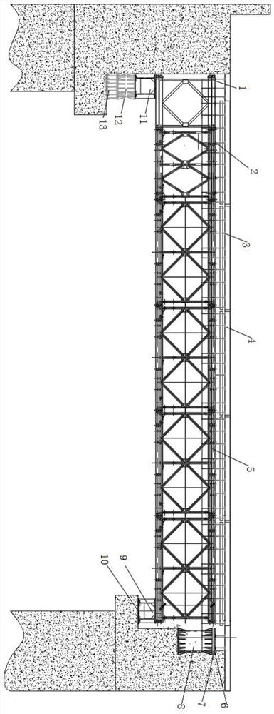
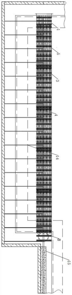
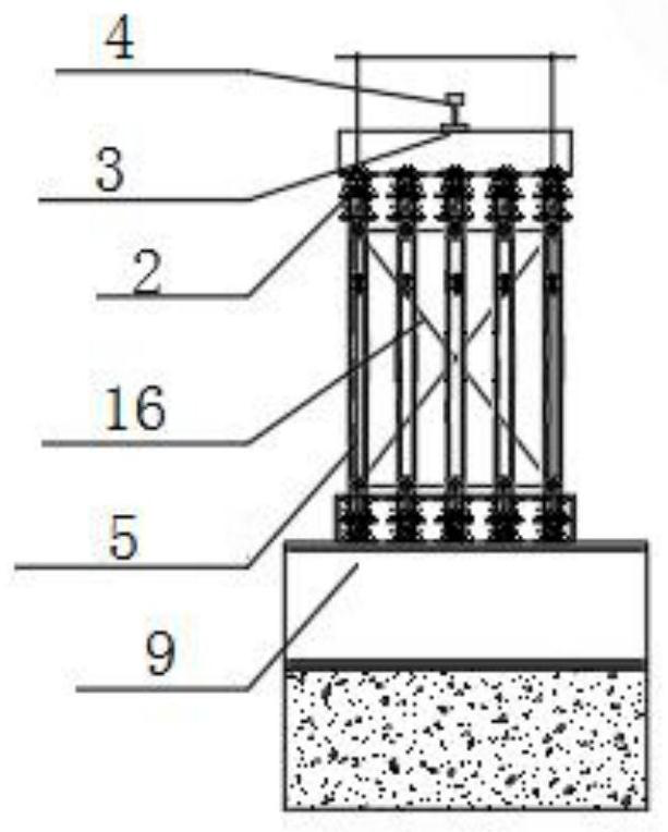
[0024] The main structure of the gantry crane combined beam device involved in this embodiment includes a first Bailey truss 1, a reinforcing chord 2, an I-beam 3, a gantry crane rail 4, a second Bailey truss 5, a steel plate 6, a flange 7, The first steel support 8, the first steel purlin 9, the adjustment steel plate 10, the second steel purlin 11, the second steel support 12, the third steel support 13, the angle steel 14, the concrete beam 15 for the rail, the support frame 16; Both ends of the second Bailey truss 5 of the group are installed with reinforcing chords 2 as the girder body of the gantry crane foundation, and the support frame 16 of X-shaped structure is fixedly installed on the second Bailey truss 5; The "meter" shape is welded and fixed to form a distribution beam. The distance between adjacent I-beams 3 does not exceed 50cm. The bottom of the I-beam 3 is welded and fixed to the reinforcing chord 2, and the top is fixed to the gantry crane rail 4 by welding t...


PUM


Abstract

The invention belongs to the technical field of shield construction, and relates to a gantry crane combined beam device and an installation method. Bailey trusses are taken as a beam body, 609 mm steel supports and I45 steel are taken as beam columns to be connected with an existing concrete structure, and members such as angle steel and the like are transversely fixed with retaining structures toenhance the overall stability of the beam body. In order to ensure that tracks are uniformly transferred to the Bailey trusses, I28 I-steel at spacing of 50 cm are used as distribution beams. The whole beam body is composed of steel structures. The bailey trusses are combined in advance before installation. Other members are blanked in position in advance according to the existing structural dimension. After a shield machine is lowered into the well, installation can be completed in 1-2 days by a crane. The device is convenient, fast and safe, does not affect normal tunneling of the shield machine, enables a gantry crane to be put into use in time, and ensures construction efficiency.

Description

Technical field: [0001] The invention belongs to the technical field of shield construction, and relates to a gantry crane combined beam device and an installation method, which are used in the installation and construction project of the shield gantry crane. When there is no concrete support beam at the enlarged end of the hoisting shaft or the support beam is blocked due to the influence of the shield hoisting After dismantling, two simple-supported track beams need to be added to ensure the normal movement of the gantry crane at the enlarged end. Background technique: [0002] During subway shield construction, it is necessary to reserve a shield hoisting port near the tunnel in the station structure for the hoisting of materials and equipment such as shield machines and segments. Due to the large size of the shield machine, the structure at the hoisting shaft needs to be enlarged. About 3m. After the shield machine is hoisted, it is necessary to install a 25T gantry cran...

Claims


Application Information

Patent Timeline
Patent Type & Authority Patents(China)
IPC IPC(8): B66C6/00
CPCB66C6/00
Inventor 任晓敏段兆臣相开将张新闯许慧鹏王威蒲万旭
Owner 中建八局轨道交通建设有限公司
Why Eureka
Try Eureka