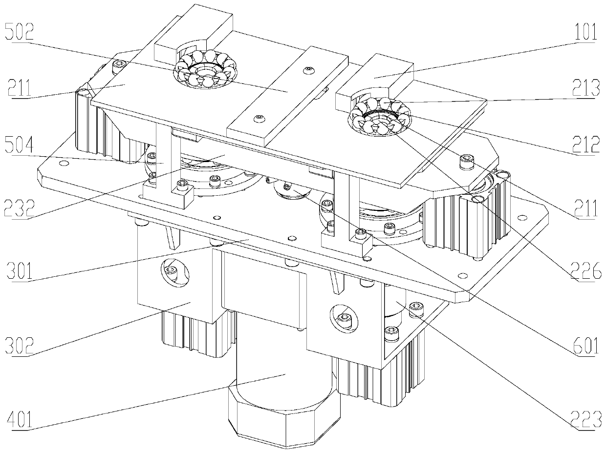
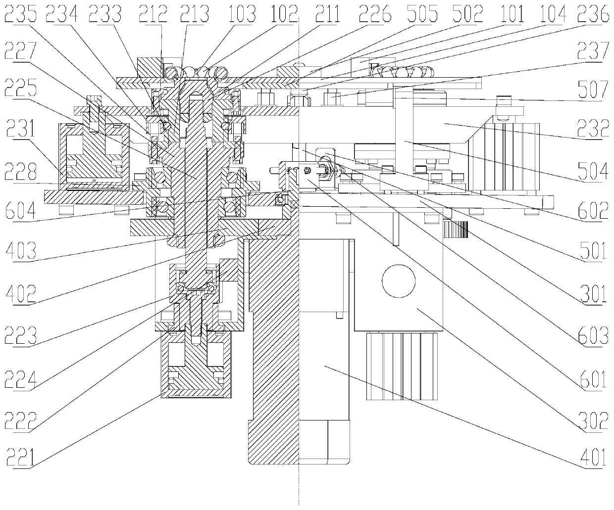
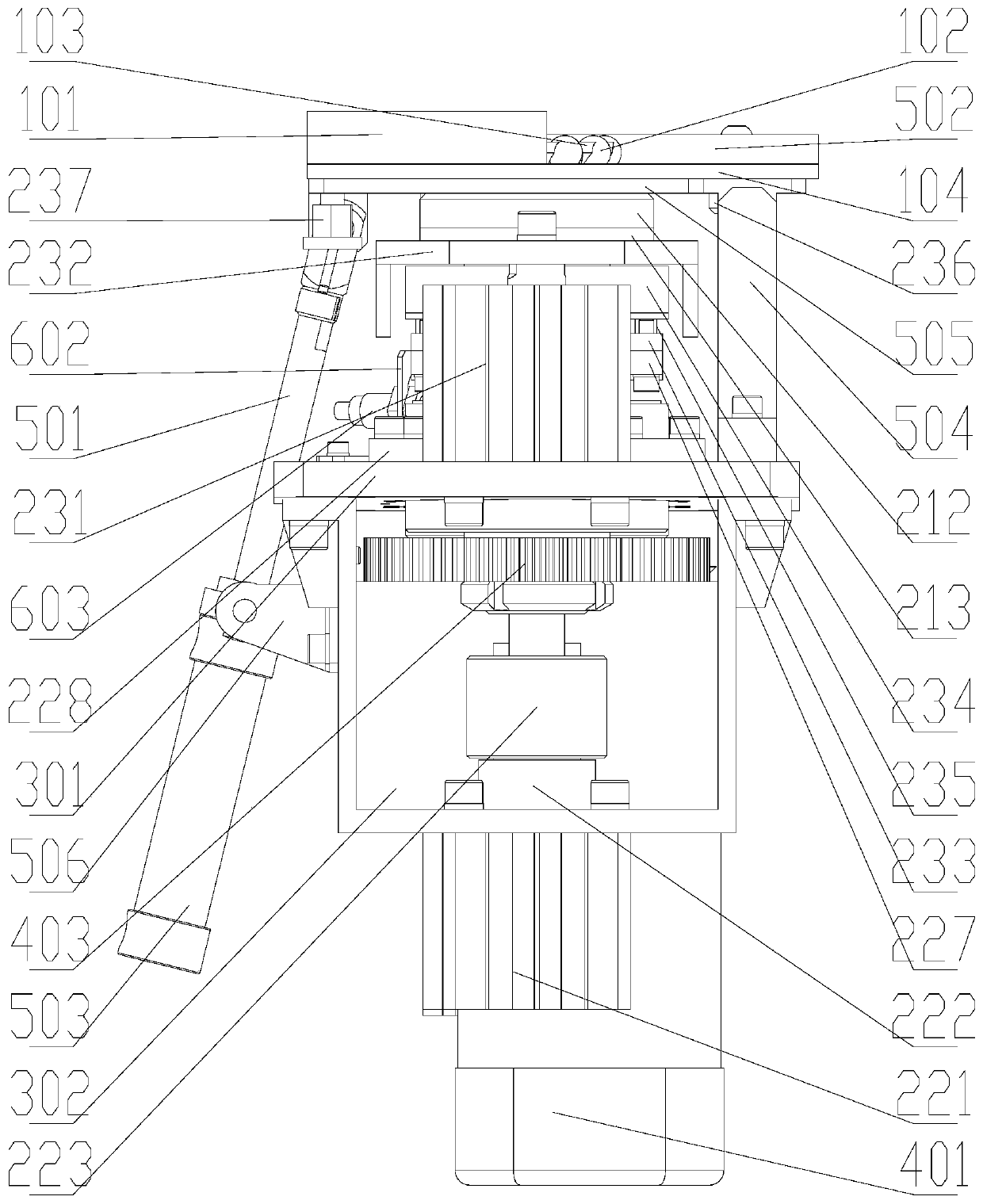
Expanding and squeezing mechanism of vehicle bearing retainer rolling body assembly device

A technology of extrusion mechanism and assembly device, applied in the direction of bearing components, shafts and bearings, mechanical equipment, etc., can solve the problems of low flexibility, difficult to meet the requirements of enterprises, and high labor costs, so as to improve the degree of flexibility and meet the needs of assembly. The effect of efficiency

Inactive Publication Date: 2020-01-31
DALIAN MARITIME UNIVERSITY
View PDF7 Cites 4 Cited by
  • Summary
  • Abstract
  • Description
  • Claims
  • Application Information

AI Technical Summary

Problems solved by technology

[0002] The installation of the rolling elements of the existing automobile wheel bearing cage mostly adopts the method of pressing the upper and lower molds. Generally, the cage and the rolling elements are placed on the installation mold, and the upper installation mold is used to press down to make the rolling elements fit into the cage. ;This kind of equipment structure and installation method is easy to cause different degrees of damage to the cage and rolling elements, and the qualified rate of the assembled products is relatively low, which is difficult to meet the requirements of the enterprise, and it is difficult to face different types of cages and rolling elements. Quick replacement of equipment mechanism to adapt to production, relatively low flexibility
[0003] In the prior art, there is still a method of manually assembling the rolling elements of the cage. This method is labor-intensive, and the labor cost is getting higher and higher. The manual assembly method is easy to cause uneven force on the cage, which leads to the completion of the assembly. The quality of the cage is uneven, and it will even seriously affect the quality and service life of the automobile wheel bearing, and the many adverse effects are incalculable

Method used


Image

  • Expanding and squeezing mechanism of vehicle bearing retainer rolling body assembly device
  • Expanding and squeezing mechanism of vehicle bearing retainer rolling body assembly device
  • Expanding and squeezing mechanism of vehicle bearing retainer rolling body assembly device

Examples


Embodiment Construction

[0068] It should be noted that, in the case of no conflict, the embodiments of the present invention and the features in the embodiments can be combined with each other. The present invention will be described in detail below with reference to the accompanying drawings and examples.

[0069] In order to make the purpose, technical solutions and advantages of the embodiments of the present invention clearer, the technical solutions in the embodiments of the present invention will be clearly and completely described below in conjunction with the drawings in the embodiments of the present invention. Obviously, the described embodiments It is only some embodiments of the present invention, but not all embodiments. The following description of at least one exemplary embodiment is merely illustrative in nature and in no way taken as limiting the invention, its application or uses. Based on the embodiments of the present invention, all other embodiments obtained by persons of ordina...


PUM


Abstract

The invention discloses an expanding and squeezing mechanism of a vehicle bearing retainer rolling body assembly device, and relates to the technical field of assembly of vehicle hub bearings, in particular to an expanding and squeezing mechanism which can achieve quick replacement of expanding modules, is suitable for various vehicle hub bearing retainers, and is used for the vehicle bearing retainer rolling body assembly device. A driving device is installed at the lower portion of a bearing structure and connected with two expanding mechanisms symmetrically installed on the bearing structure, and two squeezing mechanisms are installed at the upper portions of the two expanding mechanisms respectively; a discharge device is installed at the rear portion of the bearing structure and connected with the two expanding mechanisms and the two squeezing mechanisms at the upper portion of the bearing structure; a counting device is installed on the bearing structure and connected with the driving device. By means of the expanding and squeezing mechanism, the problems in the prior art are solved that retainers and rolling bodies are easily damaged to different degrees, the product percentof pass is relatively low, and even the quality and service life of vehicle hub bearings will be severely influenced.

Description

technical field [0001] The expansion and extrusion mechanism of the rolling body assembly device of the automobile bearing cage of the present invention relates to the technical field of automobile hub bearing assembly, especially relates to the quick replacement of expansion and tightening modules, and is applicable to the automobile bearing retention of various automobile hub bearing cages. The expansion and extrusion mechanism of the frame rolling body assembly device. Background technique [0002] The installation of the rolling elements of the existing automobile wheel bearing cage mostly adopts the method of pressing the upper and lower molds. Generally, the cage and the rolling elements are placed on the installation mold, and the upper installation mold is used to press down to make the rolling elements fit into the cage. ; This kind of equipment structure and installation method is easy to cause different degrees of damage to the cage and rolling elements, and the q...

Claims


Application Information

Patent Timeline
Patent Type & Authority Applications(China)
IPC IPC(8): F16C43/06B23P19/02
CPCB23P19/02F16C43/065
Inventor 李成求王硕
Owner DALIAN MARITIME UNIVERSITY
Why Eureka
Try Eureka