Gate valve with invisible stealing opening preventing function

An anti-theft open and functional technology, applied in the direction of preventing accidental or unauthorized actions, sliding valves, valve details, etc., can solve the problems of low safety of gate valves, easy imitation of special tools, easy damage to valves, etc. Achieve high safety performance, prevent random operation, and facilitate installation.

Pending Publication Date: 2020-01-31
CHENGDU CHUANLI INTELLIGENT FLUID CONTROL EQUIP
View PDF0 Cites 1 Cited by
  • Summary
  • Abstract
  • Description
  • Claims
  • Application Information

AI Technical Summary

Problems solved by technology

[0006] The purpose of the present invention is to overcome the disadvantages in the prior art that the anti-theft opening device of the valve can be seen at a glance from the appearance, and the special tools used are easy to be imitated and the valve is easy to be damaged, which makes the gate valve les

Method used


Image

  • Gate valve with invisible stealing opening preventing function
  • Gate valve with invisible stealing opening preventing function
  • Gate valve with invisible stealing opening preventing function

Examples


Example Embodiment

[0026] Example 1

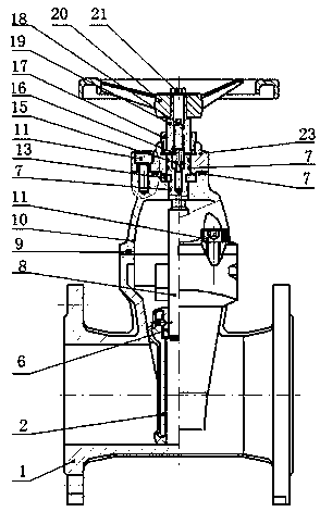
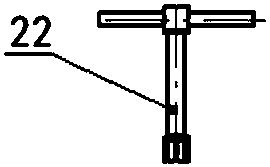
[0027] A gate valve with invisible anti-theft opening function, comprising a valve body 1, a valve cover 10 connected to the valve body 1, a gland 23 connected to the valve cover 10, and a valve stem that can be rotated to control the up and down movement of the rubber plate 2 In this implementation, the valve rod includes an upper valve rod 19 and a lower valve rod 8, the lower valve rod 8 is rotatably connected with the valve cover 10, the lower end of the lower valve rod 8 is connected with the rubber plate 2, and the lower valve rod 8 is connected with the rubber plate 2. The upper end of the valve rod 8 is provided with a first hole and a special-shaped groove 12 communicating with the first hole. A connecting block 16 is provided, and the spring 15 acts on the connecting block 16; the upper valve rod 19 is rotated and installed on the gland 23 through the pressure ring 17, the upper valve rod 19 is sleeved with a handwheel 20, and the upper valve rod 1...

Example Embodiment

[0034] Example 2

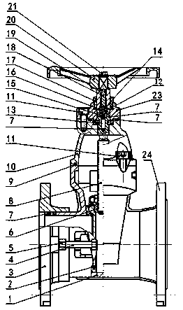
[0035] This embodiment is further optimized on the basis of Embodiment 1. In this embodiment, a sleeve 3 is sleeved coaxially at the inlet of the left end of the valve body 1 , and the sleeve 3 is sleeved after the inlet of the left end of the valve body 1 It can move left and right, and an O-ring 7 is arranged between the valve body 1 and the pipe wall of the casing 3, and the casing 3 and the valve body 1 are limited by a limiting device.

[0036] Further optimization, the limit device includes a limit screw 4 and a nut 5, the limit screw 4 is a bolt, the valve body 1 is provided with a limit plate, and the nut 5 is fixed on the sleeve 3, so The bolt can be screwed together with the nut 5 after passing through the limiting plate.

[0037] In actual use, the end of the sleeve 3 and the other end of the valve body 1 are provided with a connecting flange 24 to facilitate access to the pipe network.


PUM


Abstract

The invention discloses a gate valve with an invisible stealing opening preventing function. The gate valve comprises a valve body, a valve cover connected to the valve body, a pressure cover connected to the valve cover and a valve rod capable of rotating to further control a rubber plate to move up and down. The gate valve is characterized in that the valve rod comprises an upper valve rod and alower valve rod, the lower valve rod is rotatably connected to the valve cover, the lower end of the lower valve rod is connected to the rubber plate, a first hole and a special-shaped groove communicating to the first hole are formed in the upper end of the lower valve rod, the first hole and the lower valve rod are coaxial, a spring is arranged in the first hole, a connecting block is slidablyarranged in the special-shaped groove in a fit manner, and the spring is acted to the connecting block; the upper valve rod is rotatably mounted on the pressure cover through a pressure ring, a hand wheel is mounted on the upper valve rod in a sleeving manner, a second hole coaxial to the upper valve rod is formed in the upper valve rod, and a thread is arranged in the middle of the second hole. The gate valve is consistent to a common gate valve in appearance. Risks that a special anti-theft valve which is mounted is manually destroyed and a special tool is copied to open the gate valve can be reduced effectively. The gate valve has relatively high safety performance.

Description

technical field [0001] The invention relates to a gate valve with an invisible anti-theft opening function, which belongs to the technical field of valves. Background technique [0002] The gate valve is an opening and closing gate. The movement direction of the gate is perpendicular to the direction of the fluid. The gate valve can only be fully opened and fully closed. is 2°52'. To improve its manufacturability and make up for the deviation of the sealing surface angle during processing, this gate is called an elastic gate. [0003] When the gate valve is closed, the sealing surface can only rely on the medium pressure to seal, that is, only relying on the medium pressure to press the sealing surface of the gate to the valve seat on the other side to ensure the sealing of the sealing surface, which is self-sealing. Most gate valves are forcibly sealed, that is, when the valve is closed, the gate must be forced against the valve seat by external force to ensure the tightn...

Claims


Application Information

Patent Timeline
IPC IPC(8): F16K3/14F16K3/314F16K35/00F16K31/60F16K27/04
CPCF16K3/14F16K3/314F16K27/047F16K31/60F16K35/00
Inventor 万建华候伯忠刘志耕周艳芳方伟石泽涛陈燚
Owner CHENGDU CHUANLI INTELLIGENT FLUID CONTROL EQUIP
Why Eureka
Try Eureka