Rotor coil shaping device

A technology of shaping device and rotor coil, applied in electromechanical devices, using/manufacturing slot locking devices, manufacturing motor generators, etc., can solve the problems of high labor intensity and low efficiency of workers, reduce labor intensity of workers and improve production efficiency Effect

Pending Publication Date: 2020-01-31
HENGDIAN GRP INNUOVO ELECTRIC
View PDF0 Cites 4 Cited by
  • Summary
  • Abstract
  • Description
  • Claims
  • Application Information

AI Technical Summary

Problems solved by technology

In the prior art, coils are shaped by manual coil pressing, but the efficiency is low and the labor intensity of workers is high

Method used


Image

  • Rotor coil shaping device
  • Rotor coil shaping device

Examples


Embodiment Construction

[0014] The present invention will be further described below according to the accompanying drawings and specific embodiments.

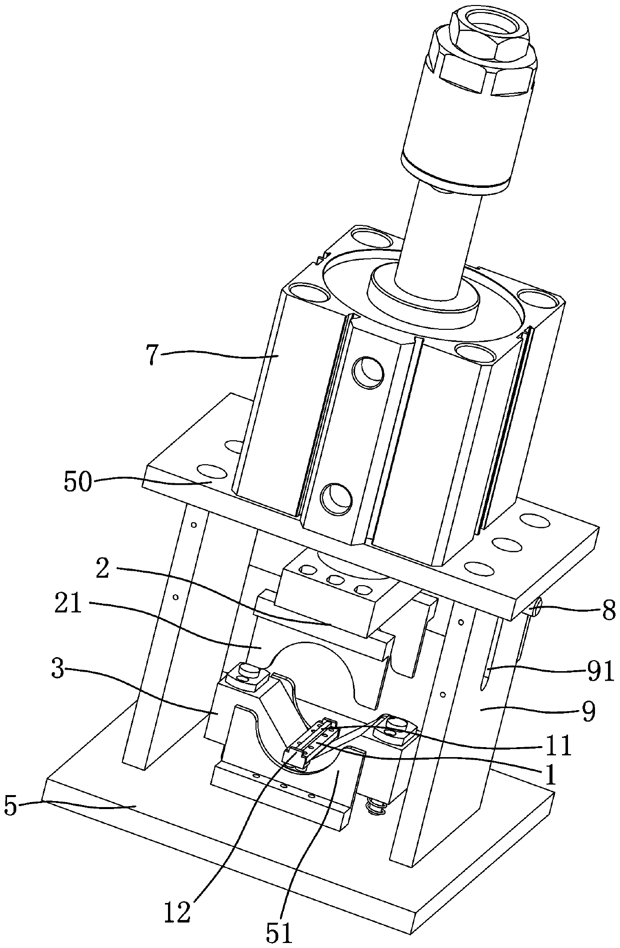
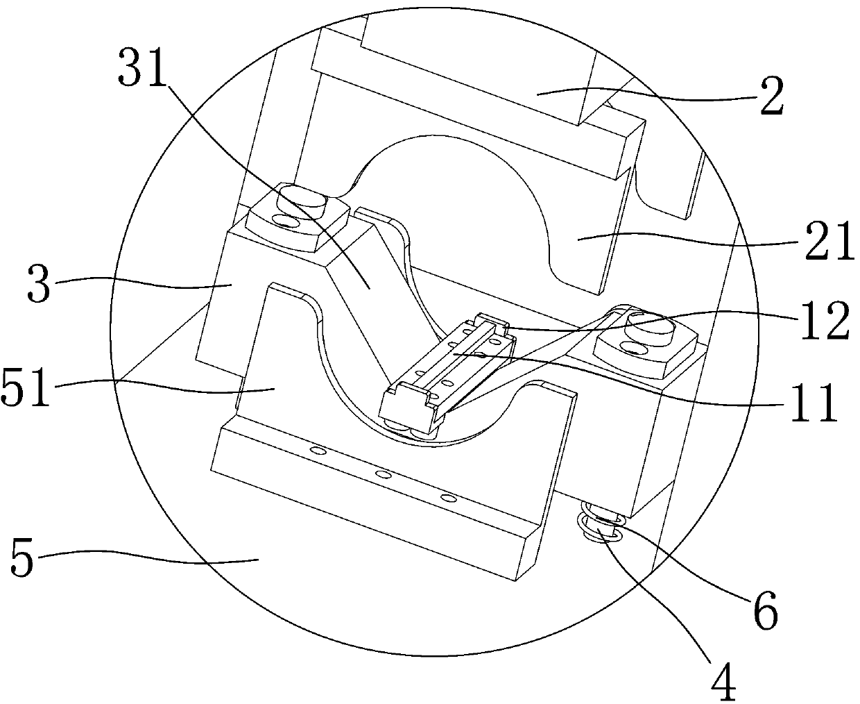
[0015] Depend on figure 1 , figure 2 As shown, a rotor coil shaping device of the present invention includes a positioning block 1 and a pressing block 2 located above the positioning block 1. The middle of the positioning block 1 is provided with a positioning protrusion 11 extending upward and arranged in the front-rear direction. The positioning protrusion The width of 11 is the same as the width of the rotor slot opening of the rotor. Both the front and rear ends of the positioning block 1 have upwardly extending limit protrusions 12. Has an arcuate slot that opens downwards.

[0016] The positioning block 1 is detachably fixed on the positioning seat 3 through screws. The positioning seat 3 is sleeved on the two vertically arranged guide rods 4. There is a spring 6, the spring 6 is sleeved on the guide rod 4, the bottom plate 5 is provided wi...


PUM


Abstract

The invention aims to provide the rotor coil shaping device which can improve production efficiency and reduce labor intensity of workers. The rotor coil shaping device is characterized in that the rotor coil shaping device comprises a positioning block and a pressing block located above the positioning block, wherein a positioning protrusion which extends upwards and is arranged in the front-backdirection is arranged in the middle of the positioning block, width of the positioning protrusion is equal to width of an opening of a rotor groove of a rotor, at least one of a front end and a rearend of the positioning block is provided with a limiting protrusion extending upwards, an upper shaping piece is fixed to a lower side of the pressing block, and the upper shaping piece is provided with an arc-shaped groove with a downward opening.

Description

technical field [0001] The invention relates to a motor rotor assembly equipment, in particular to a rotor coil shaping device. Background technique [0002] The rotor is composed of rotor iron core, rotor shaft and other components. After winding on the rotor iron core, slot labels need to be inserted into the rotor slots of the rotor iron core. The slot labels are installed along the axial direction of the rotor shaft. The copper wires at both ends will block the axial side of the rotor slot. It is necessary to press the coils at both ends of the rotor inward to expose the rotor slot, so as to facilitate the installation of slot labels. In the prior art, the method of manually pressing the coil is used to shape the coil, but the efficiency is low and the labor intensity of the worker is high. SUMMARY OF THE INVENTION [0003] The purpose of the present invention is to provide a rotor coil shaping device that can improve production efficiency and reduce labor intensity o...

Claims


Application Information

Patent Timeline
Patent Type & Authority Applications(China)
IPC IPC(8): H02K15/00
CPCH02K15/0031H02K15/0018H02K15/0037
Inventor 楼海龙舒旭东
Owner HENGDIAN GRP INNUOVO ELECTRIC
Why Eureka
Try Eureka