
Simulated load-bearing brace positioning device and method for augmented reality surgery system

A technology of positioning device and surgical system, applied in the field of simulated weight-bearing brace positioning device, can solve problems such as guiding osteotomy in three-dimensional space

Active Publication Date: 2021-07-30
北京国润健康医学投资有限公司
View PDF11 Cites 0 Cited by
  • Summary
  • Abstract
  • Description
  • Claims
  • Application Information

AI Technical Summary

Problems solved by technology

However, this means of showing different places is not suitable for guiding three-dimensional osteotomy in the narrow ankle

Method used


Image

  • Simulated load-bearing brace positioning device and method for augmented reality surgery system
  • Simulated load-bearing brace positioning device and method for augmented reality surgery system
  • Simulated load-bearing brace positioning device and method for augmented reality surgery system

Examples


Embodiment 1

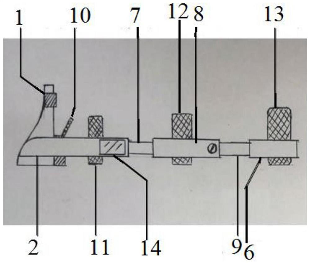
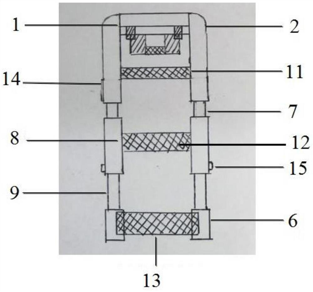
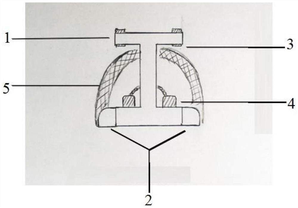
[0039] Embodiment 1, a simulated weight-bearing brace positioning device for an augmented reality surgery system according to an embodiment of the present invention, including: a simulated weight-bearing brace, a C-arm and medical imaging equipment.

[0040] The simulated weight-bearing brace is worn on the patient's ankle and is embedded with a medical image-recognizable fiducial marker locator for constructing a coordinate system. Preoperatively and postoperatively, the same driving force was selected to pressurize the soles of the feet through the simulated weight-bearing device, so as to simulate the weight-bearing state suitable for surgical evaluation and keep the relative position of the interosseous bones of the foot constant before and after the operation.

[0041] The entire structure of the simulated weight-bearing brace needs to conform to the physiological curve of the lower limbs of the human body, and can adapt to lower limbs of different lengths, meet the requir...

Embodiment 2

[0049] Embodiment 2, a method for locating a simulated weight-bearing brace for an augmented reality surgical system, comprising the following steps:

[0050] Step 1. Before the operation, a medical imaging identifiable fiducial marker locator for constructing a coordinate system is embedded in the simulated weight-bearing brace. The patient lies supine after wearing the simulated weight-bearing brace, and the C-arm is connected to the simulated weight-bearing brace.

[0051] The simulated weight-bearing brace is shown in Example 1. When wearing the simulated weight-bearing brace, the patient exposes the skin below the knee joint, and places the sole of the foot on the plantar support plate 1 to ensure that the heel is close to the bottom. The front foot fixing slider 3 and the rear foot fixing slider 4 fix the front and rear feet, and fasten the rear foot fixing belt 10; adjust the length of the adjustable connecting head 6 through the telescopic rod 9 to adapt to the length o...


PUM


Abstract

The invention discloses a positioning device for a simulated load-bearing brace used in an augmented reality surgery system. The simulated load-bearing brace is embedded with a reference mark locator; a C-arm is connected to the simulated load-bearing brace, and a data collector is fixed at the top. Including a central camera and multiple laser emitters, multiple laser emitters are projected on the surface of the patient's feet to form a projection marker locator, the central camera collects real images to provide a real environment; medical imaging equipment, which displays the simulated weight-bearing brace and the patient's foot The 3D medical image of the part provides a virtual environment, and the virtual environment is superimposed on the real environment to match and calibrate the fiducial marker locator and the projected marker locator. The invention also discloses a method for locating the simulated weight-bearing brace used in the augmented reality operation system. The beneficial effect of the present invention is to establish a corresponding matching relationship among medical imaging images, patient's ankle anatomical structure and spatial position, and imaging images through a non-invasive method and perform positioning.

Description

technical field [0001] The invention relates to the technical field of medical devices, in particular to a positioning device and method for a simulated weight-bearing brace used in an augmented reality surgery system. Background technique [0002] Hallux valgus is a foot deformity characterized by the outward deviation of the hallux beyond the normal physiological angle. It is one of the most common diseases of the forefoot. Osteotomy orthopedics is currently the most commonly used surgical method for correcting hallux valgus deformity. However, due to the inseparability of the foot structures, hallux valgus is a multi-plane compound deformity, and the pathological changes of the foot and ankle deformities are more complicated. Uncertainty in the outcome of hallux valgus surgery should be attributed to the complexity of the relationship between the first and second plantar ranks. Therefore, the ideal osteotomy for valgus valgus should be a highly individualized osteotomy b...

Claims


Application Information

Patent Timeline
Patent Type & Authority Patents(China)
IPC IPC(8): A61B90/00A61B34/10
CPCA61B34/10A61B90/39A61B2034/102A61B2034/107A61B2090/3916A61B2090/3983
Inventor 丛曰声张建中曲峰
Owner 北京国润健康医学投资有限公司
Learn More