
Heavy-load type aligning carrier roller
A technology of self-aligning rollers and rollers, which is applied in the direction of rollers, conveyors, conveyor objects, etc., can solve the problems of affecting the operation of equipment and losing the centering effect, so as to prevent the transmission objects from falling, improve friction, and improve The effect of stiffness
- Summary
- Abstract
- Description
- Claims
- Application Information
AI Technical Summary
Problems solved by technology
Method used
Image

Examples
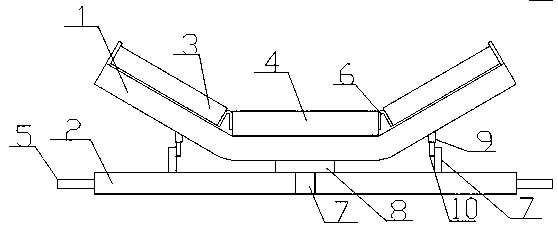
Embodiment Construction
[0011] In order to deepen the understanding of the present invention, the present invention will be further described below in conjunction with examples, which are only used to explain the present invention and do not constitute a limitation to the protection scope of the present invention.
[0012] Such as figure 1 As shown, this embodiment provides a heavy-duty self-aligning idler, including an upper beam 1 and a lower beam 2 made of high-strength metal materials, the upper beam 1 is placed on the upper end of the lower beam 2, the upper beam 1, etc. The distance is divided into three sections, wherein the inner side of the lower end of the upper beam 1 on the left and right sides is provided with an auxiliary rotating device, and the middle part of the lower end of the upper beam 1 in the middle is provided with a main supporting device, and the lower ends of the main supporting device and the auxiliary rotating device are connected with the lower beam 2 The upper beam 1 on...
PUM
 Abstract
Description
Claims
Application Information