Bottle body filling rotary positioning mechanism

A technology of positioning mechanism and bottle body, which is applied in the direction of bottle filling, safety device of filling device, packaging, etc., can solve problems such as large limitations, affecting canning operation, and poor positioning effect, so as to prevent bottle shaking and reduce Collision effect, strong automation effect

Inactive Publication Date: 2020-02-04
T LINE TECH CO LTD
View PDF0 Cites 2 Cited by
  • Summary
  • Abstract
  • Description
  • Claims
  • Application Information

AI Technical Summary

Problems solved by technology

[0002] With the development of the production industry, canning processing can be used in many fields, such as food industry, medical industry, etc. Canning needs to inject a certain amount of liquid into the bottle, and then package it. In order to meet market demand, the canning of bottles It needs to be carried out on the assembly line. When the bottle moves on the assembly line, it needs to be fixed to facilitate canning and prevent the bottle from shaking during the canning process. A positioning mechanism is required in this process. At present, the existing bottle The design of the positioning device for body canning is not reasonable enough. The fixing components will affect the canning operation to a certain extent, and the synchronization between fixing and canning cannot be guaranteed, and the positioning effect is not good, and the stability of positioning cannot be guaranteed, and the stability is not ideal. , when the bottle body runs to the bottom of the canning assembly, the positioning mechanism cannot automatically realize the positioning of the bottle, the efficiency and automation are not good, and the limitations are relatively large. Therefore, it is necessary to improve the existing technology to solve the above problems

Method used


Image

  • Bottle body filling rotary positioning mechanism
  • Bottle body filling rotary positioning mechanism
  • Bottle body filling rotary positioning mechanism

Examples


Embodiment Construction

[0016] The following will clearly and completely describe the technical solutions in the embodiments of the present invention with reference to the accompanying drawings in the embodiments of the present invention. Obviously, the described embodiments are only some, not all, embodiments of the present invention. Based on the embodiments of the present invention, all other embodiments obtained by persons of ordinary skill in the art without making creative efforts belong to the protection scope of the present invention.

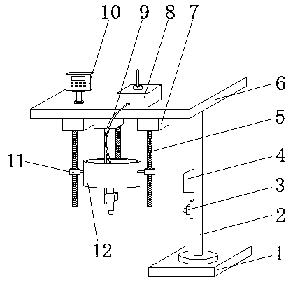
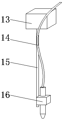
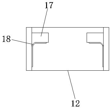
[0017] see Figure 1-5 , an embodiment provided by the present invention: a bottle filling rotary positioning mechanism, including a base 1 and a positioning cylinder 12, a vertical rod 2 is fixed at the center of the upper surface of the base 1, and a top plate 6 is welded on the upper end of the vertical rod 2 , the lower surface of top plate 6 is equilateral triangular pattern and is equipped with first motor box 7, and first motor box 7 is provided with th...


PUM


Abstract

The invention discloses a bottle body filling rotary positioning mechanism. The bottle body filling rotary positioning mechanism comprises a base and a positioning cylinder, wherein a vertical rod isfixed to the middle position of the upper surface of the base, a top plate is welded to the upper end of the vertical rod, the lower surface of the top plate is provided with first motor boxes in an equilateral triangle manner, the first motor boxes are provided with three, a screw rod is mounted on an output shaft of the lower end of each first motor box, an annular sleeve is in transmission connection with the outer wall of the screw rod, the positioning cylinder is fixed on the annular sleeve, a PLC controller and a tank filling pump are correspondingly mounted at the left side and the right side of the upper end of the top plate, the central position of the lower end of the top plate is provided with a tank filling assembly, and the interior of the tank filling assembly comprises a connecting hose. According to the bottle body filling rotary positioning mechanism, through arranging a series of structures, the device can realize the positioning and fixing of the bottle body, the positioning effect is stable, and the bottle body can be effectively prevented from shaking, the positioning operation of the bottle body can be automatically realized according to the positioning mechanism, the efficiency is high, and the automation degree is strong.

Description

technical field [0001] The invention relates to the technical field of detection and auxiliary equipment of a filling production line, in particular to a bottle filling rotary positioning mechanism. Background technique [0002] With the development of the production industry, canning processing can be used in many fields, such as food industry, medical industry, etc. Canning needs to inject a certain amount of liquid into the bottle, and then encapsulate it. In order to meet market demand, the canning of bottles It needs to be carried out on the assembly line. When the bottle moves on the assembly line, it needs to be fixed to facilitate canning and prevent the bottle from shaking during the canning process. A positioning mechanism is required in this process. At present, the existing bottle The design of the positioning device for body canning is not reasonable enough. The fixing components will affect the canning operation to a certain extent, and the synchronization betw...

Claims


Application Information

Patent Timeline
Patent Type & Authority Applications(China)
IPC IPC(8): B67C3/24B67C3/26B67C3/00B67C3/22
CPCB67C3/007B67C3/22B67C3/24B67C3/26
Inventor 李文涛
Owner T LINE TECH CO LTD
Why Eureka
Try Eureka