Yarn waxing device for knitting machines

A weaving machine and yarn technology, applied in textiles and papermaking, etc., can solve the problems of wax block consumption, uneven waxing on the yarn surface, etc.

Active Publication Date: 2020-02-04
抚州市中小企业服务有限公司
View PDF10 Cites 3 Cited by
  • Summary
  • Abstract
  • Description
  • Claims
  • Application Information

AI Technical Summary

Problems solved by technology

[0006] In order to overcome the disadvantage that the yarn rubs against the same position of the wax block for a long time, which will lead to excessive consumption of the wax block, and when the yarn is in contact with the wax block, the wax on the surface of the yarn will be uneven due to the different contact positions. The technical problem to be solved To: Provide a yarn waxing device for knitting machines that can avoid direct contact of yarns with wax blocks, reduce the consumption of wax blocks, and can evenly wax the surface of yarns

Method used


Image

  • Yarn waxing device for knitting machines
  • Yarn waxing device for knitting machines
  • Yarn waxing device for knitting machines

Examples


Embodiment 1

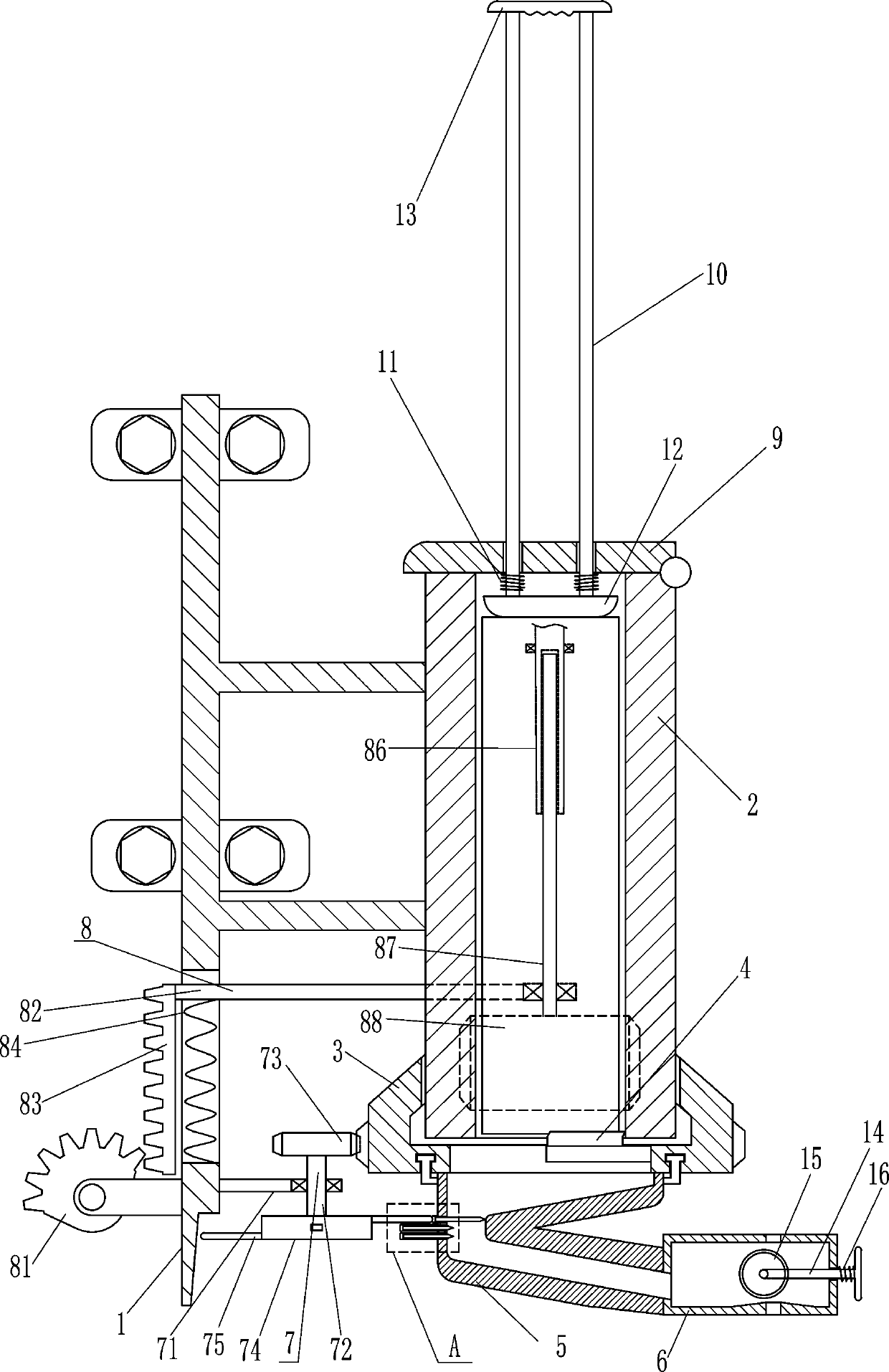
[0023] A yarn waxing device for knitting machines, please refer to figure 1 , image 3 and Figure 5 , including mounting frame 1, cylinder 2, outer ring gear 3, scraper 4, discharge pipe 5, waxing frame 6 and chopping device 7, cylinder 2 is installed on the right side of mounting frame 1, and the lower part of cylinder 2 rotates The outer gear ring 3 is equipped with an outer gear ring 3, and a scraper 4 for scraping the wax block is installed in the outer gear ring 3. The scraper 4 is located at the lower part of the cylinder 2, and the lower part of the outer gear ring 3 is rotated. The pipe 5 communicates with the outer ring gear 3, the right side of the discharge pipe 5 is equipped with a waxing frame 6 for storing wax debris, the waxing frame 6 communicates with the discharge pipe 5, and the left side of the outer ring gear 3 is provided with a chopping device 7, wherein the chopping device 7 is used to chop the scraped wax block.

[0024] The shredding device 7 incl...

Embodiment 2

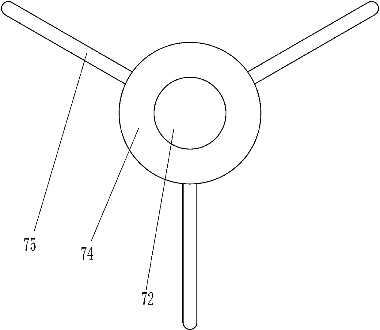
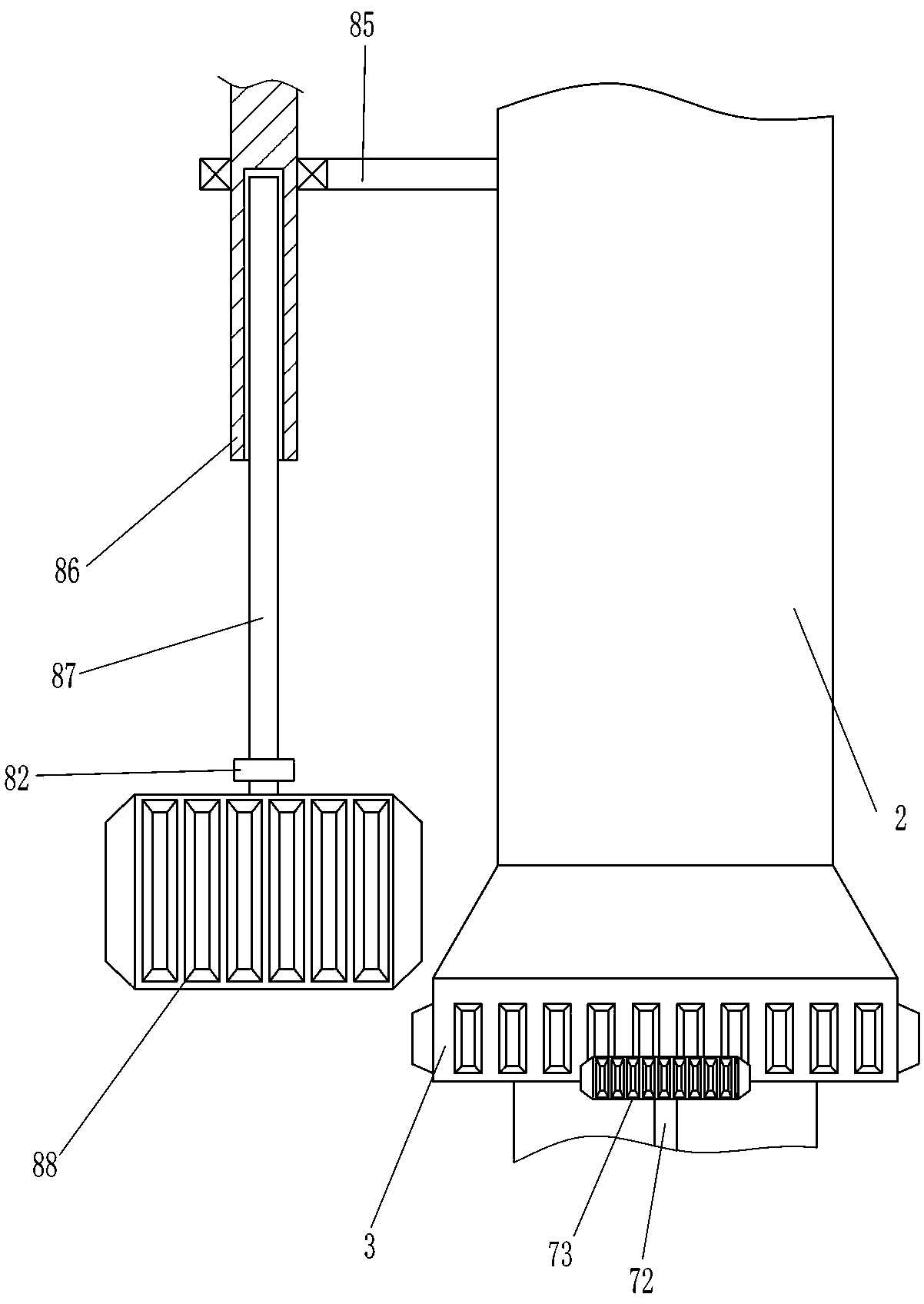
[0027] On the basis of Example 1, please refer to figure 1 , figure 2 , Figure 6 and Figure 7 , also includes driving device 8, and driving device 8 includes sector gear 81, movable rod 82, rack 83, first spring 84, cross bar 85, hexagonal cylinder 86, hexagonal rod 87 and column gear 88, mounting frame 1. A sector gear 81 is installed on the lower left side, and the power source of the knitting machine is connected with the sector gear 81. The sliding type of the mounting frame 1 bottom is provided with a movable rod 82, and a rack 83 is vertically installed on the left end of the movable rod 82. The rack 83 is connected to the Sector gear 81 is meshed, first spring 84 is connected between the bottom of movable bar 82 and mounting frame 1, cross bar 85 is installed on cylinder 2 rear side upper part, and cross bar 85 rear end rotation type is provided with hexagonal cylinder 86, and knitting machine The power source is connected with the hexagonal cylinder 86, and the h...

Embodiment 3

[0030] On the basis of Example 2, please refer to figure 1 and Figure 4, also includes a cover plate 9, a slide bar 10, a second spring 11, a pressure plate 12 and a handle 13, the top right side of the cylinder 2 is rotatably provided with a cover plate 9, and the cover plate 9 is slidably provided with two slide bars 10 , the lower part of the slide bar 10 is located in the cylinder 2, the second spring 11 is connected between the lower part of the slide bar 10 and the bottom of the cover plate 9, the second spring 11 is in a compressed state, the bottom of the slide bar 10 is equipped with a pressure plate 12, and the top of the slide bar 10 A handle 13 is installed.

[0031] Also comprise pull bar 14, guide wheel 15 and the 3rd spring 16, waxing frame 6 right wall sliding type is provided with pull bar 14, pull bar 14 left ends are equipped with guide wheel 15, between pull bar 14 right parts and waxing frame 6 outer right walls A third spring 16 is connected between th...


PUM


Abstract

The invention relates to a yarn waxing device, in particular to a yarn waxing device for knitting machines. The technical problem is how to design a yarn waxing device for knitting machines, which helps prevent a yarn from directly contacting a wax block, allows the consumption of the wax block to be reduced, and provides uniform waxing for the surface of the yarn. The yarn waxing device for knitting machines comprises a mounting rack, a cylinder and the like; the cylinder is mounted on the right side of the mounting rack. The wax block can be scraped into a sheet through a scraper; the scrapped sheet can be crushed into wax granules through cooperation of a contact rod and an elastic plate, so that a yarn can be more fully contacted with the wax granules; a sector gear can drive a cylindrical gear to intermittently cooperate with an outer gear ring, so that an operator does not need to manually shift the outer gear ring; a pressing plate cooperates with a second spring, so that the operator does not need to press the wax block by hand; a yarn guide wheel cooperates with the yarn, so that the surface of the yarn can be uniformly waxed.

Description

technical field [0001] The invention relates to a yarn waxing device, in particular to a yarn waxing device for a knitting machine. Background technique [0002] Yarn is waxed to allow hairiness to lie down on the yarn while increasing production efficiency. It can also reduce hairiness blocking pinholes and needle cylinders during the weaving process, causing rotten needles and other defects. [0003] After the yarn is waxed, it can reduce the friction of some parts and mechanical wear, thereby reducing the friction coefficient, making the yarn evenly tensed, reducing the yarn breakage rate, increasing the weaving rate and improving the product quality. quality. [0004] The current waxing method is to directly fix the wax block so that the wax block is in contact with the yarn, and then the yarn is driven by the knitting machine to slide and rub directly against the wax block. After the yarn contacts the wax block, the wax can be applied to the yarn. This method will ca...

Claims


Application Information

Patent Timeline
Patent Type & Authority Applications(China)
IPC IPC(8): D02J3/18
CPCD02J3/18
Inventor 曾海英
Owner 抚州市中小企业服务有限公司
Why Eureka
Try Eureka