Dustproof Rod Ends

A technology of end joints and dust-proof rods, which is applied in the direction of bearings, shafts, bearings, bearing components, etc., can solve the problems of complex structure and low reliability of rod end joint bearings, achieve mature use and installation methods, improve service life and Reliability, effect of avoiding frictional interference

Active Publication Date: 2022-01-25
台州科锦轴承有限公司 +1
View PDF8 Cites 0 Cited by
  • Summary
  • Abstract
  • Description
  • Claims
  • Application Information

AI Technical Summary

Problems solved by technology

[0005] The purpose of the present invention is to provide a dust-proof rod end joint bearing, which can solve the problems of complex structure and low reliability of the rod end joint bearing in the prior art

Method used


Image

  • Dustproof Rod Ends
  • Dustproof Rod Ends
  • Dustproof Rod Ends

Examples


Embodiment 1

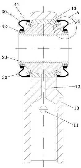
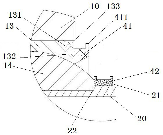
[0050] Embodiment 1 of the dust-proof rod-end joint bearing in the present invention: the dust-proof rod-end joint bearing in the present invention can effectively block dust and the like from intruding into the bearing inner ring 14 and bearing outer ring 13 through the dust-proof cover 30 provided thereon. The bearing working surface between them reduces the wear of the bearing working surface and improves the service life of the bearing.

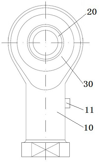
[0051] Such as figure 1 and figure 2 As shown, the main components of the dust-proof rod end joint bearing include a rod end body 10. The rod end body 10 has the same structure as the rod end body 10 of other rod end joint bearings in the prior art, and rod end eyes are arranged on it. A bearing outer ring 13 is installed in the eye hole of the rod end, and the bearing outer ring 13 is relatively fixedly arranged with the rod end body 10 . A bearing inner ring 14 is movable in the bearing outer ring 13. There is a spherical fitting sur...

Embodiment 2

[0072] Embodiment 2 of the dust-proof rod end joint bearing in the present invention: the difference from the above embodiment is that in this embodiment, a connecting sleeve forming a support shaft is installed on the side of the inner ring of the bearing, and the connecting sleeve is located on the inner ring of the bearing. outside of the shaft mounting hole. The connecting sleeve can be fixed on the side of the bearing inner ring by welding, or the connecting sleeve can be fixed on the side of the bearing inner ring by setting a flange on the connecting sleeve, and the connecting sleeve can be fixed on the side of the bearing inner ring by screwing. A rotating mating surface for mounting the rotating support ring is formed.

Embodiment 3

[0073] Embodiment 3 of the dust-proof rod end joint bearing in the present invention: the difference from the above embodiments is that in this embodiment, a ring groove is directly processed on the extension section of the shaft sleeve to cooperate with the rotating support ring. The groove bottom of the ring groove corresponds to form a rotating mating surface.


PUM


Abstract

The invention provides a dust-proof rod end joint bearing, which can solve the problems of complex structure and low reliability of the rod end joint bearing in the prior art. Dust-proof rod end joint bearing includes: rod end body, bearing outer ring, bearing inner ring, dust cover; inner edge support structure and outer edge support structure; inner edge support structure includes rotating support ring and support shaft, rotating support ring and The support shaft is rotated and matched; the support shaft is assembled with the inner ring of the bearing to prevent rotation; the support shaft includes a rotating matching surface, the rotating matching surface is a cylindrical surface, and the rotating matching surface is located at the axial outer side of the shaft installation hole; It is assembled on the rotating matching surface of the support shaft, and is fixedly and sealedly connected to the inner edge of the dust cover. The inner diameter of the rotating supporting ring is larger than the outer diameter of the rotating matching surface, which is used to make the gap between the rotating supporting ring and the rotating matching surface. There is an interval, and the dimension of the interval can not only ensure that the rotating support ring and the supporting shaft are rotatably matched, but also meet the sealing requirements.

Description

technical field [0001] The invention relates to the technical field of bearings, in particular to a dust-proof rod-end joint bearing. Background technique [0002] Rod end joint bearings, also known as fisheye joints, consist of an inner ring and an outer ring with a sliding spherical surface as the contact surface, and are mainly used in low-speed swinging motions, tilting motions, and rotating motions. When the rod end joint bearing is in use, the inner ring and the outer ring slide relatively. There is no sealing structure on the outer side of the inner ring and the outer ring. The dust in the work site will enter the bearing working surface through the gap between the inner and outer rings, making the bearing Severe abrasive wear on the working face and failure. [0003] In order to solve the problem of the failure of the rod end joint bearing due to abrasive wear, the technicians proposed to add a dust cover outside the bearing and use the dust cover to prevent dust fr...

Claims


Application Information

Patent Timeline
Patent Type & Authority Patents(China)
IPC IPC(8): F16C23/04F16C33/74
CPCF16C23/043F16C33/723F16C33/74
Inventor 占松华孔静静邱明张平赵银龙曾伟林
Owner 台州科锦轴承有限公司
Why Eureka
Try Eureka