
Novel baffling rod heat exchanger device

A technology of baffle rods and heat exchangers, which is applied to the types of heat exchangers, heat exchanger shells, indirect heat exchangers, etc., and can solve problems such as short service life, increased energy consumption, and rupture of welded joints between tubes and tube sheets

Pending Publication Date: 2020-02-04
YONGSHENG MACHINERY IND KUNSHAN
View PDF0 Cites 0 Cited by
  • Summary
  • Abstract
  • Description
  • Claims
  • Application Information

AI Technical Summary

Problems solved by technology

[0003] In order to facilitate the assembly of tube bundles, the tube holes of the baffles must be larger than the tube diameters, and the tubes are not fixed tightly. Therefore, this type of heat exchanger is prone to vibration, which often breaks the welded joints between the tubes and the tube sheets, and the tube holes at the baffles The tube wears out and has a short service life
The most effective way to reduce vibration is to shorten the distance between the baffles or reduce the velocity of the fluid, but increasing the number of baffles will lead to an increase in shell side resistance and heat transfer dead zone, increased energy consumption, and a smaller effective heat transfer area. To reduce the flow rate of the fluid will increase the size of the heat exchanger, reduce the efficiency and increase the cost, so the above two methods are uneconomical

Method used


Image

  • Novel baffling rod heat exchanger device
  • Novel baffling rod heat exchanger device
  • Novel baffling rod heat exchanger device

Examples


Embodiment

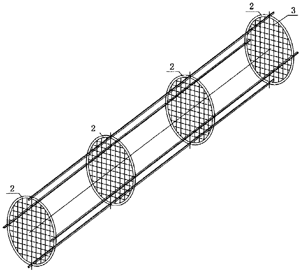
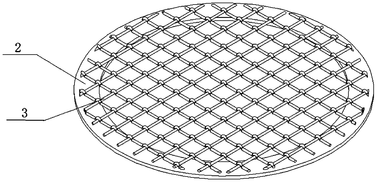
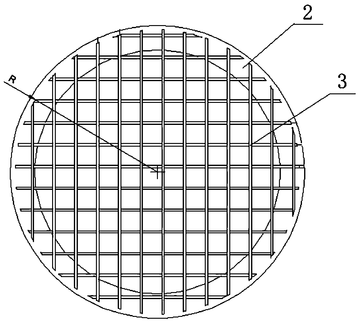
[0026] Such as Figure 1-6 As shown, a new type of baffle rod heat exchanger device includes a shell 1, a baffle ring 2 is provided on the inner wall of the shell 1, and a plurality of baffle rods are arranged on the baffle ring 2 in the direction of the X-axis and the Y-axis respectively. 3. A plurality of baffle rods 3 arranged on the X-axis and Y-axis are provided with a plurality of heat exchange tubes 4 .

[0027] Preferably, a plurality of baffle rods 3 arranged in the X-axis and Y-axis directions are connected to the baffle ring 2 in a grid shape.

[0028] Preferably, the baffle rod 3 in the X-axis direction is arranged at the upper end of the baffle rod 3 in the Y-axis direction.

[0029] Preferably, the heat exchange tubes 4 run through the grid-like baffle rods 3 .

[0030] Preferably, the distance between the plurality of baffle rods 3 arranged along the X-axis and the Y-axis matches the diameter of the plurality of heat exchange tubes 4 .

[0031] Preferably, a ...


PUM


Abstract

The invention discloses a novel baffling rod heat exchanger device. The novel baffling rod heat exchanger device comprises a housing, wherein a baffling ring is arranged on the inner wall of the housing; a plurality of baffling rods are arranged on the baffling ring in the X-axis direction and the Y-axis direction respectively; and a plurality of heat exchange tubes are arranged in the baffling rods arranged in the X-axis direction and the Y-axis direction. The novel baffling rod heat exchanger device has the advantages that: a baffling rod heat exchanger supported by a baffling plate is replaced by a rod support, so that the problem of induced vibration of fluid is solved, and a heat transfer dead zone is eliminated due to the change of the flowing direction and state of the fluid. Due tothe structure, the speed of housing pass fluid is certainly increased, and the flow speed can be increased by over two times compared with that of a single arch baffle. Due to the acceleration of theflow speed, the shearing force of the fluid on a liquid film outside a tube is increased, so that the liquid film is thinned; and the baffling rods interfere the flow of the fluid, and vortex and turbulence are generated to play a role in thinning the liquid film, so that the heat transfer coefficient is greatly increased.

Description

technical field [0001] The invention relates to the technical field of heat exchangers, in particular to a novel baffle rod heat exchanger device. Background technique [0002] The general baffle structure is bow-shaped baffles, and a few have circular baffles, rectangular baffles, baffle rods, grille baffles and other baffles, and most of them are bow-shaped baffles. , the simplified flow state of the fluid in the shell is as follows Figure 7 , 8 As shown, the area marked with A in the figure is the main heat transfer area. In this area, the fluid impacts the tube bundle laterally, showing cross-flow heat transfer. It can reach a turbulent state at a lower Re number, and about 85% of the heat transfer is in this area. The area marked with B is the downstream area, where the fluid and the tube bundle flow in parallel, and the heat transfer completed in this area only accounts for about 15%; the area marked with C is the vortex area, and the fluid stays in place in this are...

Claims


Application Information

Patent Timeline
Patent Type & Authority Applications(China)
IPC IPC(8): F28D7/16F28F9/22F28F9/24
CPCF28D7/163F28F9/22F28F9/24F28F2009/224
Inventor 王建江谢金山谭雅丹
Owner YONGSHENG MACHINERY IND KUNSHAN
Learn More