Helix tube heat exchanger

A heat exchanger and spiral tube technology, applied in the field of heat exchangers, can solve the problems of low heat exchange efficiency, large flow resistance, easy scaling, etc., and achieve the effects of small flow resistance, enhanced radial mixing, and less scaling

Inactive Publication Date: 2009-06-10
苏州吉来冷冻空调设备配件有限公司
View PDF0 Cites 4 Cited by
  • Summary
  • Abstract
  • Description
  • Claims
  • Application Information

AI Technical Summary

Problems solved by technology

However, there is a deflection part in the "bow" heat exchange tube. When the cooling medium flows to the deflection part, a dead zone is formed, and it is also easy to scale, and the flow resistance is also relatively large.
Therefore, its heat transfer efficiency is low and its lift is small.

Method used


Image

  • Helix tube heat exchanger
  • Helix tube heat exchanger

Examples


Embodiment Construction

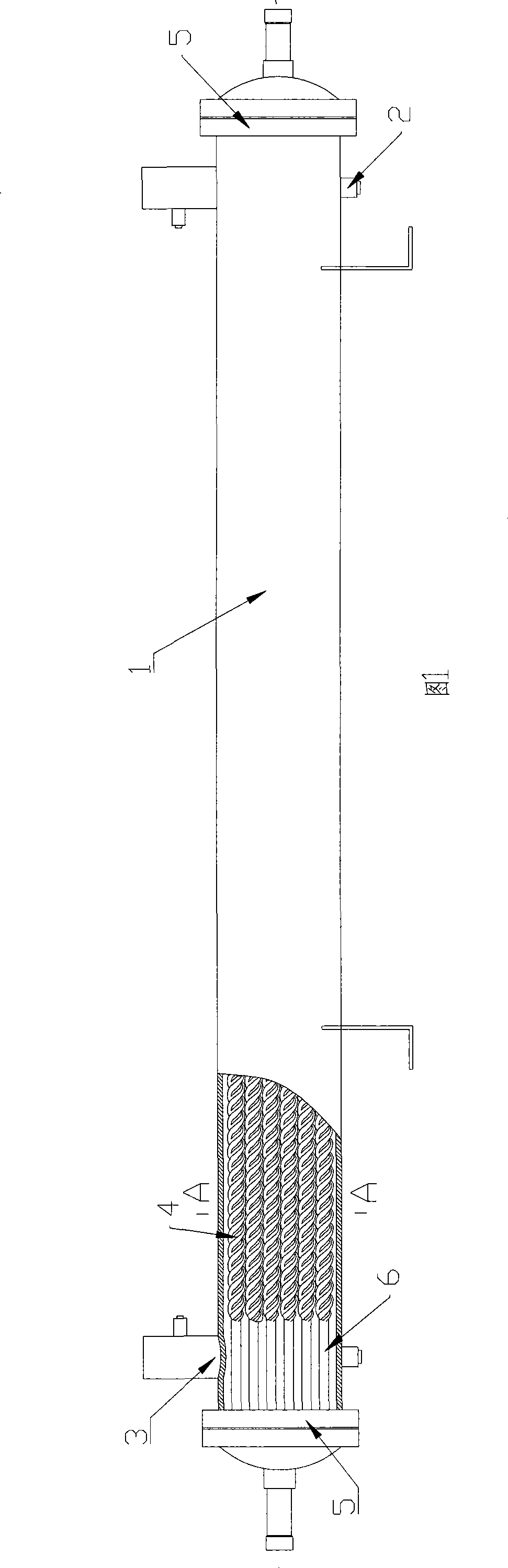
[0009] Referring to the spiral tube heat exchanger shown in Figures 1 and 2, the two ends of the outer tube 1 are respectively provided with a water inlet 2 and a water outlet 3 . There are a plurality of spiral heat exchange tubes 4 inside the outer tube, flange plates (tube plates) 5 are hermetically connected to both ends of the outer tubes, and circular tube sections 6 at both ends of the heat exchange tubes are hermetically connected to the flange plates. Both the outer tube and the spiral heat exchange tube are straight tubes.

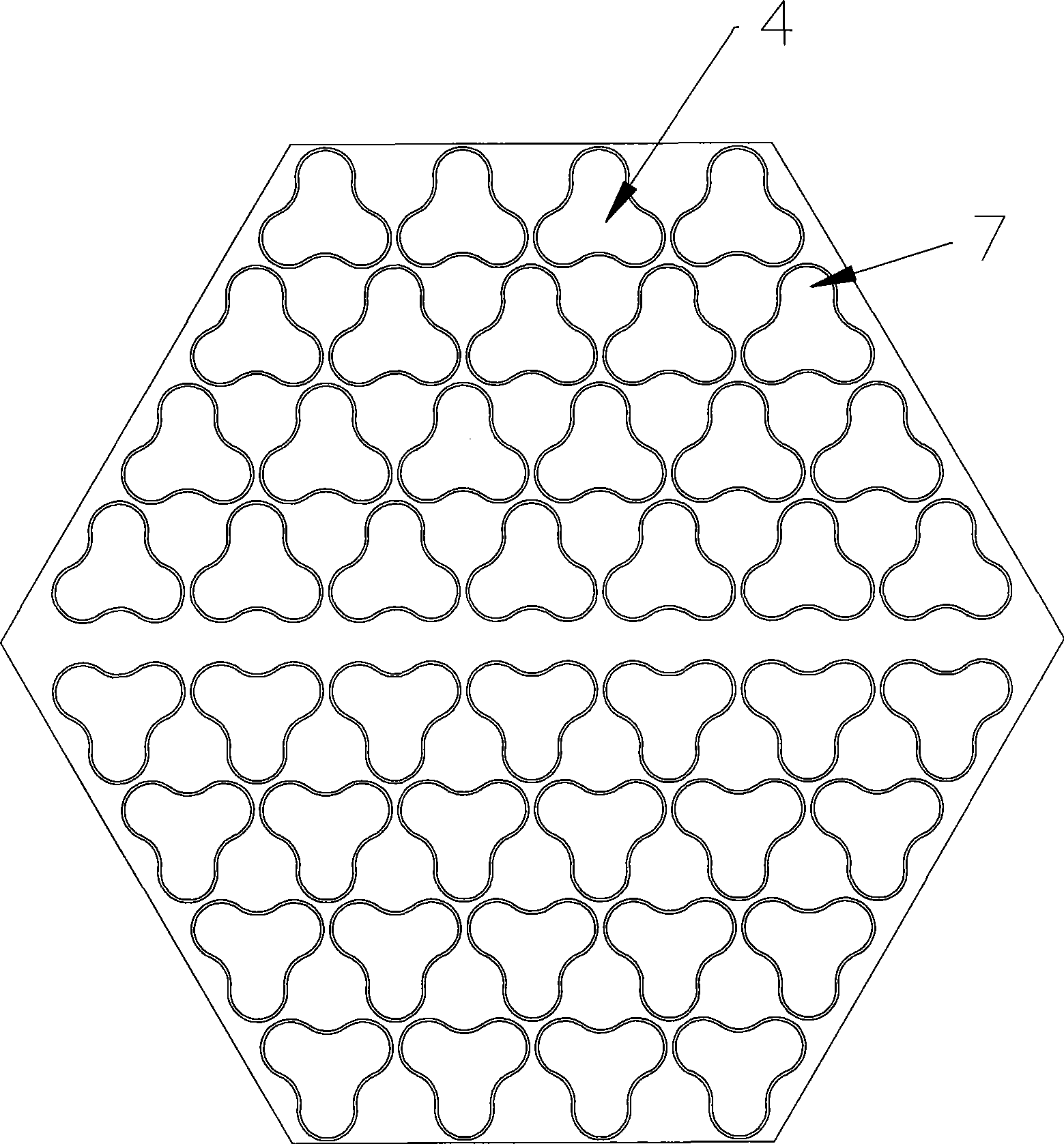
[0010] The tube wall in the middle section of the heat exchange tube has three helical lines 7 evenly distributed on the same cross section, and the helical lines 7 between adjacent heat exchange tubes are in contact. There are threads (not shown) on the inner surface of the heat exchange tubes, and the direction of the threads is opposite to the helical direction of the helix. There are 50-70 (for example, 60) threads on the same cross section ...


PUM


Abstract

The invention provides a heat exchanger with high heat exchanging efficiency, small resistance, difficult scale formation and small vibration, comprising an external tube with a water inlet and outlet and a plurality of spiral heat exchange tubes in the external tube; wherein the two ends of the external tube are respectively connected with a tube plate hermetically; the two ends of the heat exchange tubes are hermetically connected to the tube plate; the external tube and the spiral heat exchange tubes are straight tubes; the walls of the heat exchange tubes are provided with three spiral lines uniformly distributed on a same section; and the spiral lines between adjacent heat exchange tubes are contacted.

Description

technical field [0001] The invention relates to a heat exchanger. Background technique [0002] Ordinary heat exchanger, including the outer tube with water inlet and outlet and the "bow" shaped heat exchange tube inside the outer tube. The two ends of the outer tube are sealed and connected with the tube plate, and the two ends of the heat exchange tube are sealed with the tube plate. . The cooled medium flows in the heat exchange tube, and the cooling medium (shell-side fluid) flows in the outer tube of the heat exchange tube to realize heat exchange between the cooling medium and the cooled medium. However, there is a baffle in the "bow" heat exchange tube. When the cooling medium flows to the baffle, a dead zone is formed, and it is easy to scale and the flow resistance is also relatively large. Therefore, its heat transfer efficiency is low and its head is small. Contents of the invention [0003] The purpose of the present invention is to provide a heat exchanger ...

Claims


Application Information

Patent Timeline
Patent Type & Authority Applications(China)
IPC IPC(8): F28D7/10
Inventor 陈辉
Owner 苏州吉来冷冻空调设备配件有限公司
Why Eureka
Try Eureka