
Pipe bundle supporting structure of pipe shell type heat exchanger

A technology of shell-and-tube heat exchanger and support structure, which is applied in the direction of heat exchanger shell, heat transfer modification, heat exchange equipment, etc., and can solve the problems of low heat transfer coefficient, large fluid resistance, and flow dead angle in the shell side, etc. Achieve the effect of increasing heat transfer coefficient, improving heat transfer efficiency, and increasing heat transfer temperature difference

Pending Publication Date: 2019-03-08
FOSHAN UNIVERSITY
View PDF8 Cites 0 Cited by
  • Summary
  • Abstract
  • Description
  • Claims
  • Application Information

AI Technical Summary

Problems solved by technology

[0002] The bow-shaped baffles usually provided in the shell-and-tube heat exchangers in the prior art, as a supporting part for the heat exchange tubes, are usually processed from steel plates and are bow-shaped, and the bow is cut off by 1 / It is made of 4 to 1 / 3 parts, the fluid passes through the gap, and tube holes are set on the arcuate baffles for the heat exchange tubes to pass through, so as to support the heat exchange tubes, and several baffles are arranged at equal intervals along the axial direction , the directions of the notches of two adjacent baffles are opposite, and the shell-side fluid flows through the upper and lower notches or the left and right notches alternately, forming an "S"-shaped flow, but such a flow method is prone to flow dead angles, and the heat transfer area cannot be fully utilized , so the heat transfer coefficient of the shell side is low, easy to scale, and the fluid resistance is large. Moreover, when the fluid flows through the tube bundle laterally, the tube may induce vibration and damage the reliability of the connection between the tube and the tube sheet.

Method used


Image

  • Pipe bundle supporting structure of pipe shell type heat exchanger

Examples


Embodiment Construction

[0018] The idea, specific structure and technical effects of the present invention will be clearly and completely described below in conjunction with the embodiments and accompanying drawings, so as to fully understand the purpose, features and effects of the present invention. Apparently, the described embodiments are only some of the embodiments of the present invention, rather than all of them. Based on the embodiments of the present invention, other embodiments obtained by those skilled in the art without creative efforts belong to The protection scope of the present invention. In addition, all connection relationships mentioned in this article do not refer to the direct connection of components, but mean that a better connection structure can be formed by adding or reducing connection accessories according to specific implementation conditions. The various technical features in the invention can be combined interactively on the premise of not conflicting with each other. ...


PUM


Abstract

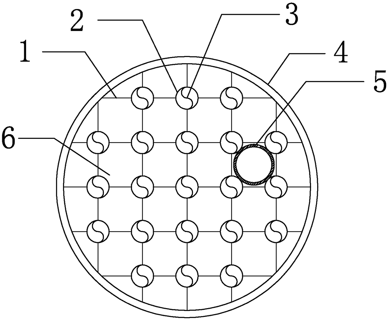
The invention discloses a pipe bundle supporting structure of a pipe shell type heat exchanger. The pipe bundle supporting structure comprises a circular ring arranged on the periphery of the supporting structure and cyclone pipes arranged in the circular ring; the cyclone pipes are arranged in a square mode; the adjacent cyclone pipes are connected in a welded mode through steel sheets; the cyclone pipes close to the circular ring and the circular ring are connected in a welded mode through the corresponding steel sheets; and a through hole capable of allowing a heat exchanging pipe to pass through is jointly defined by every four adjacent cyclone pipes and the corresponding steel sheets for connecting the cyclone pipes, wherein the outer walls of the four adjacent cyclone pipes are tangent to the outer wall of the heat exchanging pipe to clamp the heat exchanging pipe penetrating through the through hole to support the heat exchanging pipe. Meanwhile, the cyclone pipes can further allow fluids to pass through, the fluids pass through the cyclone pipes and then generate a cyclone to replace near-wall and far-wall fluids in a shell, the heat transfer coefficient of shell side fluids is increased, and the overall heat exchange efficiency is improved; and in addition, the shell side fluids can further flow through gaps between the cyclone pipes and the heat exchanging pipes, andflow in the axial direction of the heat exchanging pipes, and thus induced vibration generated when the fluids transversely wash heat exchanging pipe bundles is avoided.

Description

technical field [0001] The invention belongs to the field of heat transfer equipment, and relates to a tube bundle support structure of a shell-and-tube heat exchanger. Background technique [0002] The bow-shaped baffles usually provided in the shell-and-tube heat exchangers in the prior art, as a supporting part for the heat exchange tubes, are usually processed from steel plates and are bow-shaped, and the bow is cut off by 1 / It is made of 4 to 1 / 3 parts, the fluid passes through the gap, and tube holes are set on the arcuate baffles for the heat exchange tubes to pass through, so as to support the heat exchange tubes, and several baffles are arranged at equal intervals along the axial direction , the directions of the notches of two adjacent baffles are opposite, and the shell-side fluid flows through the upper and lower notches or the left and right notches alternately, forming an "S"-shaped flow, but such a flow method is prone to flow dead angles, and the heat transf...

Claims


Application Information

Patent Timeline
Patent Type & Authority Applications(China)
IPC IPC(8): F28F9/013F28F13/06
CPCF28F9/013F28F13/06
Inventor 黄德斌钟嘉恒
Owner FOSHAN UNIVERSITY
Learn More