
Shell type heat exchanger configured from composite tubes of figured pattern card

A combined tube and heat exchanger technology, applied in the direction of heat exchanger types, heat exchanger shells, indirect heat exchangers, etc., can solve the problem of low natural frequency of heat exchange tubes, shortened life of heat exchangers, poor anti-vibration capabilities, etc. problem, to achieve the effect of reducing the flow dead zone and leakage dead zone, increasing the effective heat transfer area, and improving the effective heat transfer area

Inactive Publication Date: 2006-04-19
MAOMING MAOGANG ELECTRIC POWER EQUIP FACTORY
View PDF0 Cites 4 Cited by
  • Summary
  • Abstract
  • Description
  • Claims
  • Application Information

AI Technical Summary

Problems solved by technology

[0005] Horizontal scouring of the tube bundle will induce vibration of the heat exchange tubes, which is the main cause of heat exchange tube rupture and tube sheet leakage, thus greatly shortening the life of the entire heat exchanger;
[0006] The flow resistance is large, and the resistance is small when there are few baffles, but the natural frequency of the heat exchange tube is low, the anti-vibration ability is poor, and the heat transfer coefficient K value is also greatly reduced, and the resistance increases when the number of baffles increases;
[0007] The dirt in the fluid is easy to deposit on the surface of the heat exchange tube, the K value decreases, and the heat transfer effect becomes poor

Method used


Image

  • Shell type heat exchanger configured from composite tubes of figured pattern card
  • Shell type heat exchanger configured from composite tubes of figured pattern card
  • Shell type heat exchanger configured from composite tubes of figured pattern card

Examples


Embodiment Construction

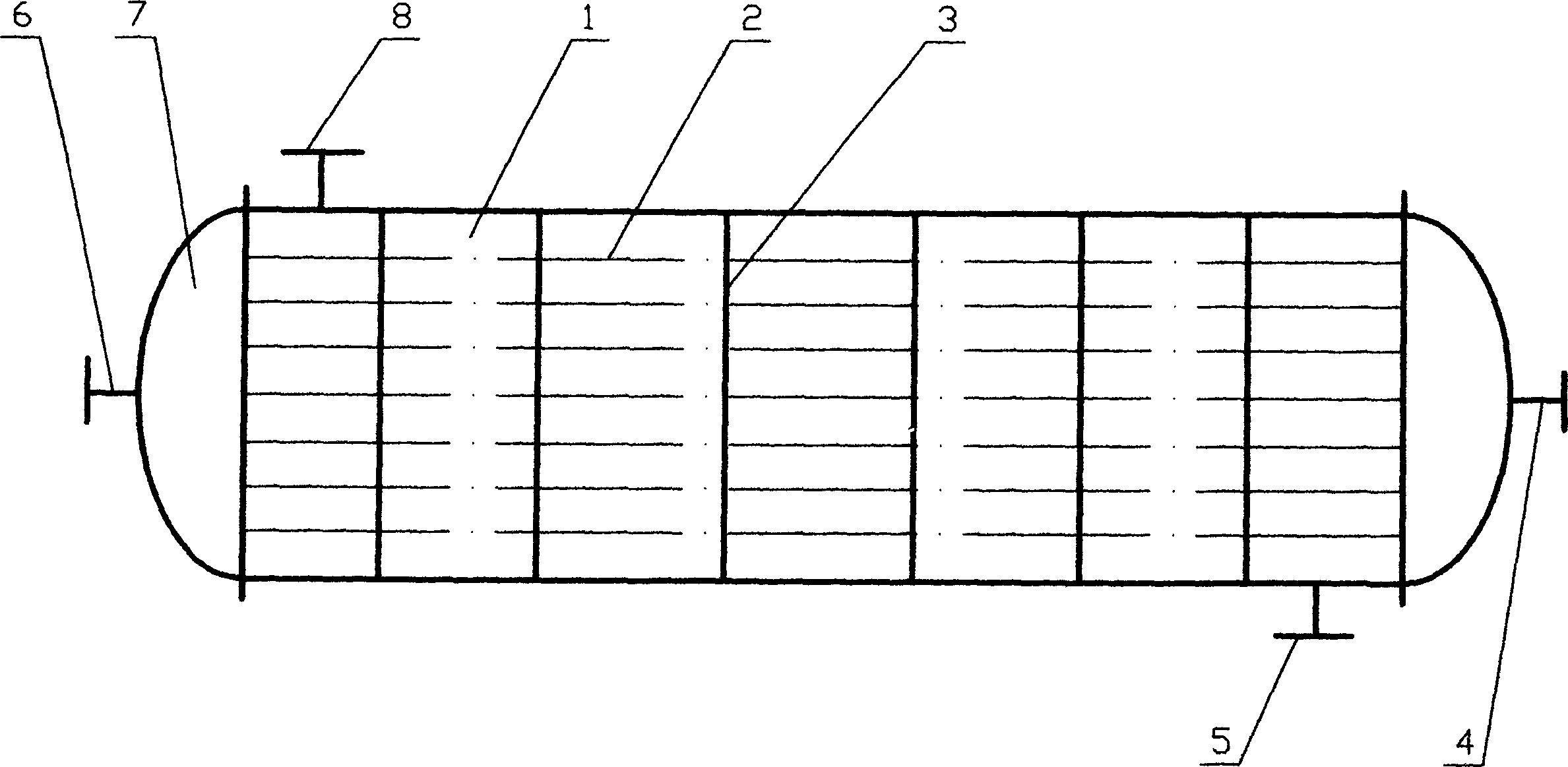
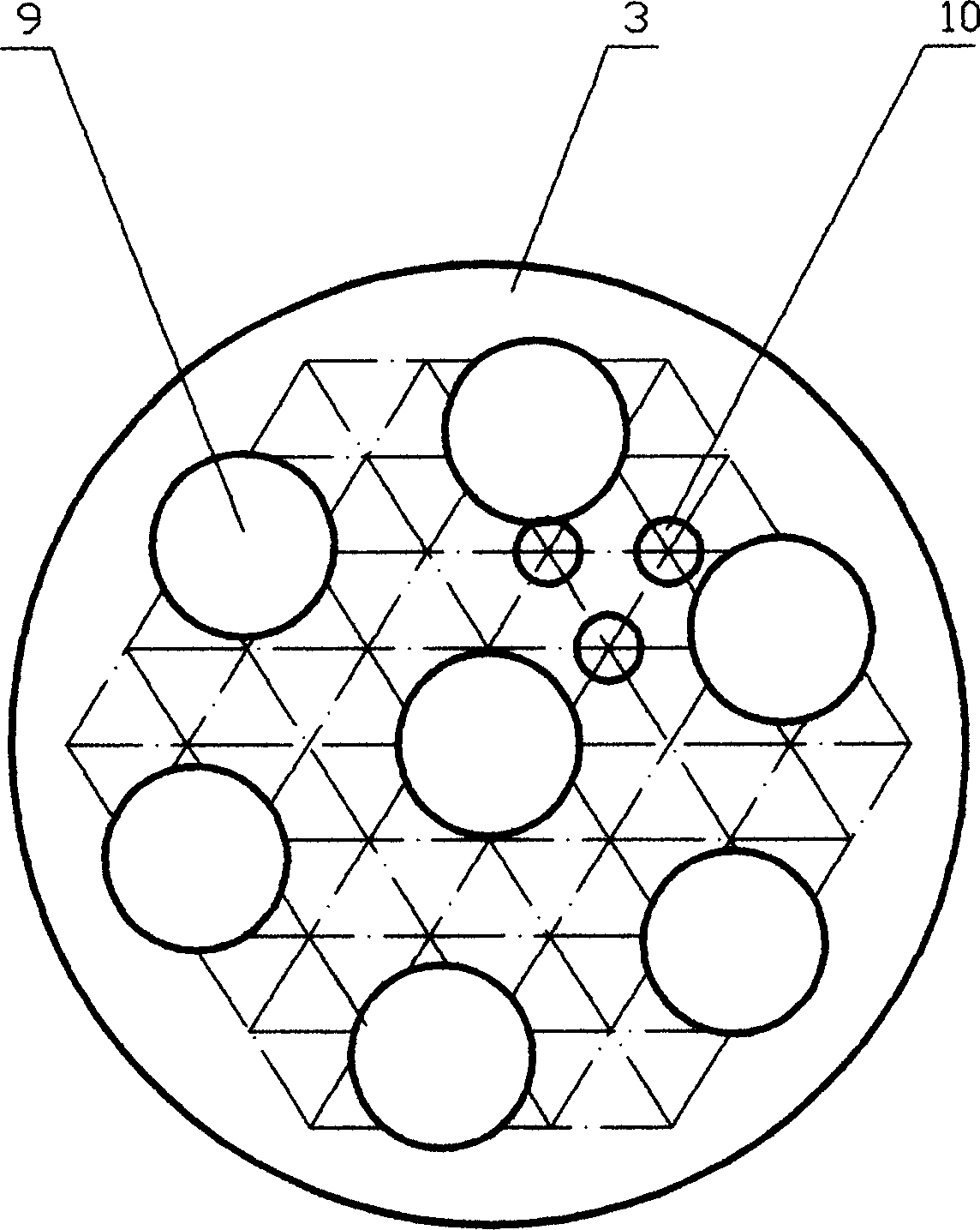
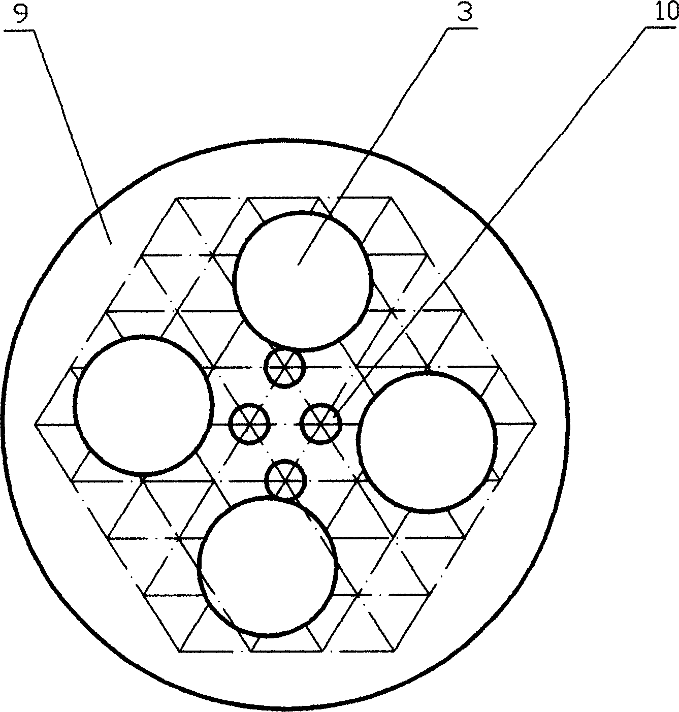
[0021] refer to figure 1 , figure 2 , image 3 , flower-plate combined shell-and-tube heat exchanger, including shell [1], cover [7], tube bundle [2] and tube-side inlet and outlet [6], [4] on the cover and shell on the shell Cheng import and export [5], [8], in the shell [1], there are flower plates [3] whose outer diameter corresponds to the inner diameter of the shell, and the flow direction of the flower plate [3] is perpendicular to the tube bundle [2]. The flower board [3] has several through holes [9], and the positions of the through holes [9] between adjacent flower boards [3] are staggered. The shell-side fluid flow is organized by staggering the positions of the through holes [9] of each flower plate [3], and the flow direction and velocity of the fluid are constantly changed to generate mixed flow and improve heat exchange efficiency.

[0022] The through hole [9] of flower plate is circular, see figure 2 , image 3 , and the projection of each through hole ...


PUM


Abstract

A tube ¿C shell heat changer with card combination consists of shell, seal head, tube bundle. Tube form entrance and exit on seal head and shell form entrance and exit on seal head. It features that card with external diameter corresponding to internal diameter of shell is set in sequence in shell, card is vertical to flow direction of tube bundle, a numbers of through holes are opened on each card and positions of through holes on two adjacent cards are staggered.

Description

technical field [0001] The invention relates to a flower plate combined shell and tube heat exchanger, which belongs to the technical field of power and energy. Background technique [0002] The traditional shell-and-tube heat exchanger is a baffle-type structure. Generally, a number of baffles are set on the shell side, so that the fluid is repeatedly reversed on the shell side and flushes the heat exchange tube bundle vertically, so as to increase the flow velocity and turbulence of the fluid and improve Shell side heat transfer effect. [0003] However, this kind of baffle heat exchanger has the following fatal shortcomings because the shell-side fluid scours the tube bundle laterally and constantly changes the flow direction: [0004] The presence of flow dead zones and leakage dead zones on the shell side reduces the effective heat transfer area by 25 to 30 percent; [0005] Horizontal scouring of the tube bundle will induce vibration of the heat exchange tubes, which...

Claims


Application Information

Patent Timeline
Patent Type & Authority Applications(China)
IPC IPC(8): F28F9/24F28D1/04
Inventor 黄素逸叶加贵赖学江李权
Owner MAOMING MAOGANG ELECTRIC POWER EQUIP FACTORY
Learn More