
Speed limiting method, device and system, electronic equipment and computer readable storage medium

A rate-limiting and rate-limiting technology, which is applied in the computer and communication fields, can solve the problems that the speed limit performance of the stand-alone version cannot meet business needs, and the processing performance cannot be exceeded.

Inactive Publication Date: 2020-02-04
TENCENT TECH (SHENZHEN) CO LTD
View PDF9 Cites 8 Cited by
  • Summary
  • Abstract
  • Description
  • Claims
  • Application Information

AI Technical Summary

Problems solved by technology

[0003] In the prior art, a single server (stand-alone) is usually used for speed limit, but the processing performance of the stand-alone version cannot exceed the performance of the physical machine itself, therefore, the speed limit performance of the stand-alone version cannot meet some business needs

Method used


Image

  • Speed limiting method, device and system, electronic equipment and computer readable storage medium
  • Speed limiting method, device and system, electronic equipment and computer readable storage medium
  • Speed limiting method, device and system, electronic equipment and computer readable storage medium

Examples


Embodiment Construction

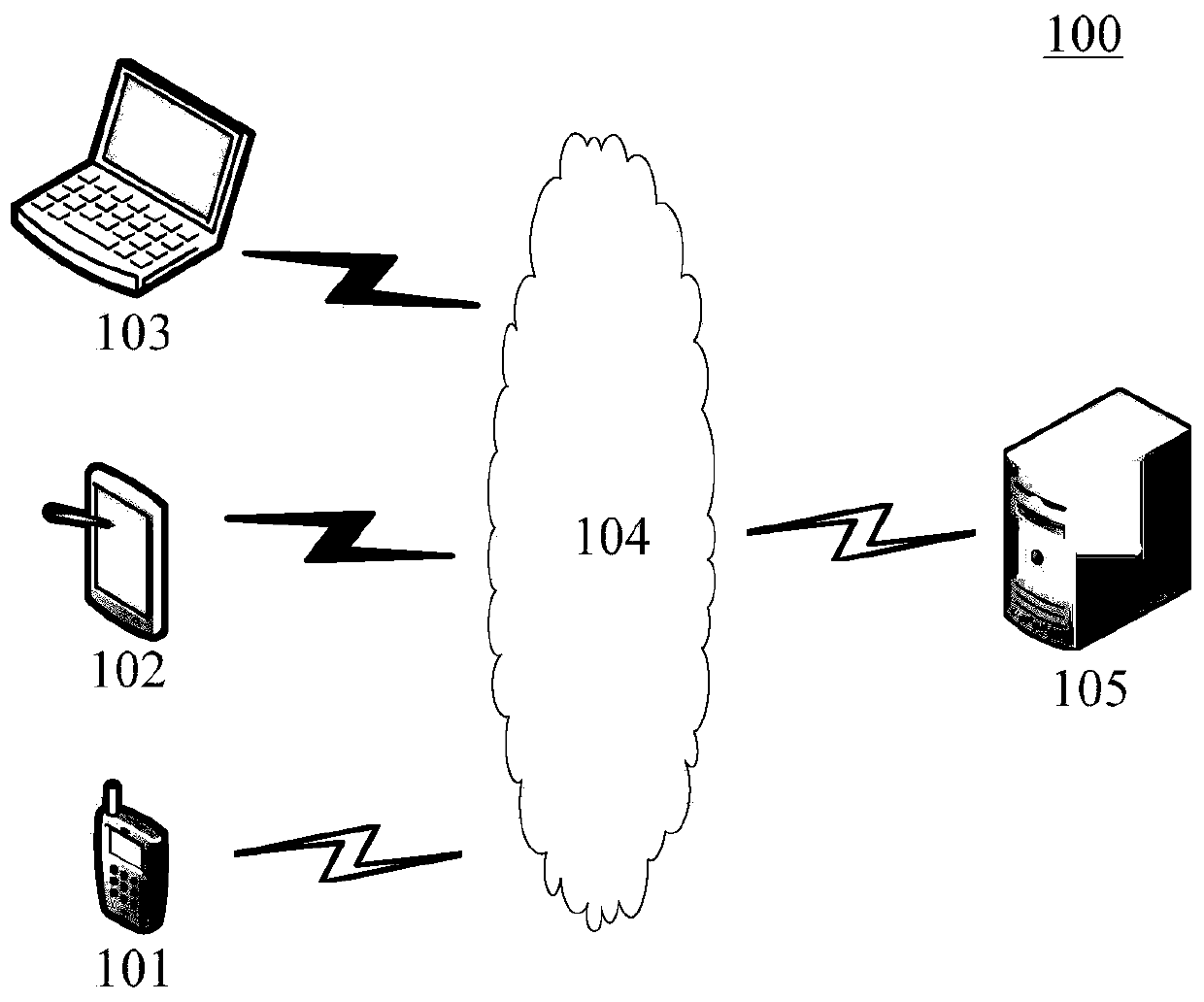
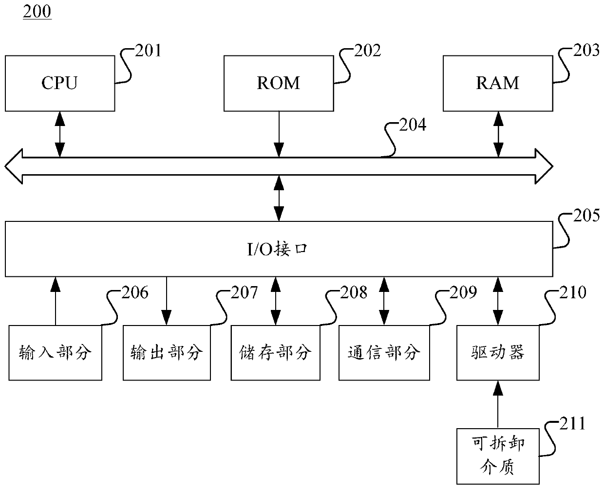
[0030] Example embodiments will now be described more fully with reference to the accompanying drawings. Example embodiments may, however, be embodied in many forms and should not be construed as limited to the examples set forth herein; rather, these embodiments are provided so that this disclosure will be thorough and complete and will fully convey the concept of example embodiments to those skilled in the art.

[0031] Furthermore, the described features, structures, or characteristics may be combined in any suitable manner in one or more embodiments. In the following description, numerous specific details are provided in order to give a thorough understanding of embodiments of the present disclosure. However, those skilled in the art will appreciate that the technical solutions of the present disclosure may be practiced without one or more of the specific details, or other methods, components, means, steps, etc. may be employed. In other instances, well-known methods, ap...


PUM


Abstract

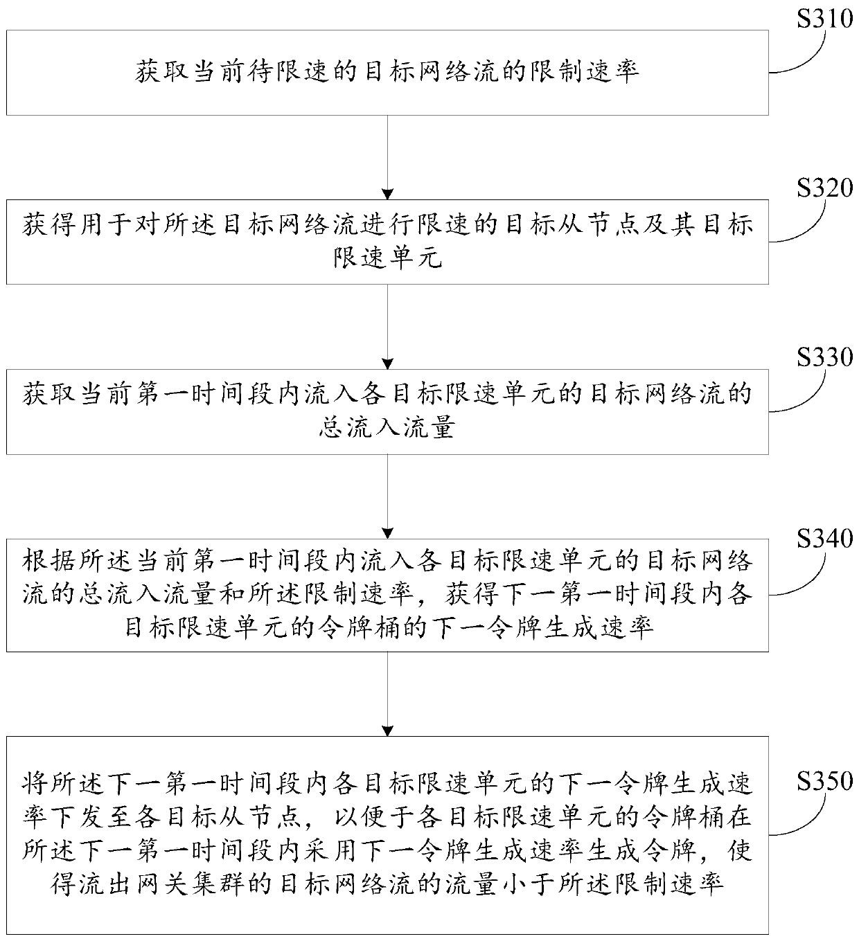
The embodiment of the invention provides a speed limiting method, device and system, electronic equipment and a computer readable storage medium. The method comprises the following steps: acquiring alimiting rate of a current target network flow to be limited in speed; obtaining a target slave node for limiting the speed of the target network flow and a target speed limiting unit of the target slave node; obtaining the total inflow flow of the target network flow flowing into each target speed limiting unit in the current first time period; obtaining the next token generation rate of the token bucket of each target speed limiting unit in the next first time period according to the total inflow flow and the limiting rate of the target network flow flowing into each target speed limiting unit in the current first time period; and issuing the next token generation rate of each target speed limiting unit in the next first time period to each target slave node, so that the token bucket ofeach target speed limiting unit generates a token by adopting the next token generation rate in the next first time period, and the flow of the target network flow flowing out of the gateway cluster is less than the limit rate.

Description

technical field [0001] The present disclosure relates to the field of computer and communication technologies, and in particular, relates to a speed limiting method, device and system, electronic equipment, and a computer-readable storage medium. Background technique [0002] When developing a high-concurrency system, technologies such as caching, degradation, and current / speed limiting are usually used to protect the system. Among them, the purpose of current limiting is to protect the system by limiting the rate of concurrent access / requests, or limiting the rate of requests within a time window. Once the limit rate is reached, the service can be refused, queued or waited, and downgraded. . [0003] In the prior art, a single server (stand-alone) is usually used for speed limit, but the processing performance of the stand-alone version cannot exceed the performance of the physical machine itself. Therefore, the speed limit performance of the stand-alone version cannot mee...

Claims


Application Information

Patent Timeline
Patent Type & Authority Applications(China)
IPC IPC(8): H04L12/819H04L12/813H04L47/21H04L47/20
CPCH04L47/215H04L47/20
Inventor 陈力陆元伟马志
Owner TENCENT TECH (SHENZHEN) CO LTD
Learn More