Garment Hanging System Multi-rod Lifting Arm

A pull-rod, lift-arm technology, applied in the field of multi-tie-rod lift arms of a garment hanging system, can solve problems such as the influence of the connection end, the shortened service life of the transmission belt, and the large span.

Active Publication Date: 2021-03-09
衡阳腾飞内衣有限公司
View PDF6 Cites 0 Cited by
  • Summary
  • Abstract
  • Description
  • Claims
  • Application Information

AI Technical Summary

Problems solved by technology

[0003] The lifting arm is connected to the transmission wheel through the motor. One of the two transmission wheels is active and the other is driven. The transmission wheel is covered with a transmission belt, and the outer side of the transmission belt is provided with a push rod. Under the action of the transmission belt, transmission wheel and motor, the hanger roller is pushed up. , due to the large span between the two transmission wheels, when the push rod drives the pulley of the hanger to rise, the transmission belt will be forced inward by the reaction force, which will cause the push rod to fall off
[0004] Due to the structure of the shell, the existing lifting arm usually uses a transmission belt with unclosed ends. The two ends of the transmission belt pass through the cavity for secondary closure. The secondary closed transmission belt is not easy to connect, and the service life of the transmission belt after connection is also relatively short. reduce, and at the same time, the connection end will also have an impact on the cooperation with the transmission wheel
[0005] Nowadays, most lifting arms are integral structures, which are troublesome to install and disassemble, and it is not easy to install belts at the same time.

Method used


Image

  • Garment Hanging System Multi-rod Lifting Arm
  • Garment Hanging System Multi-rod Lifting Arm
  • Garment Hanging System Multi-rod Lifting Arm

Examples


Embodiment Construction

[0029] The present invention will be further described below in conjunction with specific embodiment and accompanying drawing, set forth more details in the following description so as to fully understand the present invention, but the present invention can be implemented in many other modes different from this description obviously, Those skilled in the art can make similar promotions and deductions based on actual application situations without violating the connotation of the present invention, so the content of this specific embodiment should not limit the protection scope of the present invention.

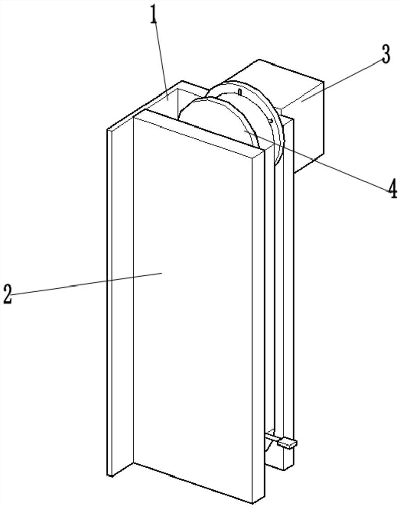
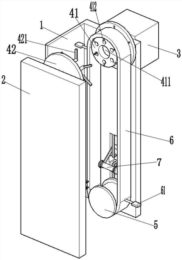
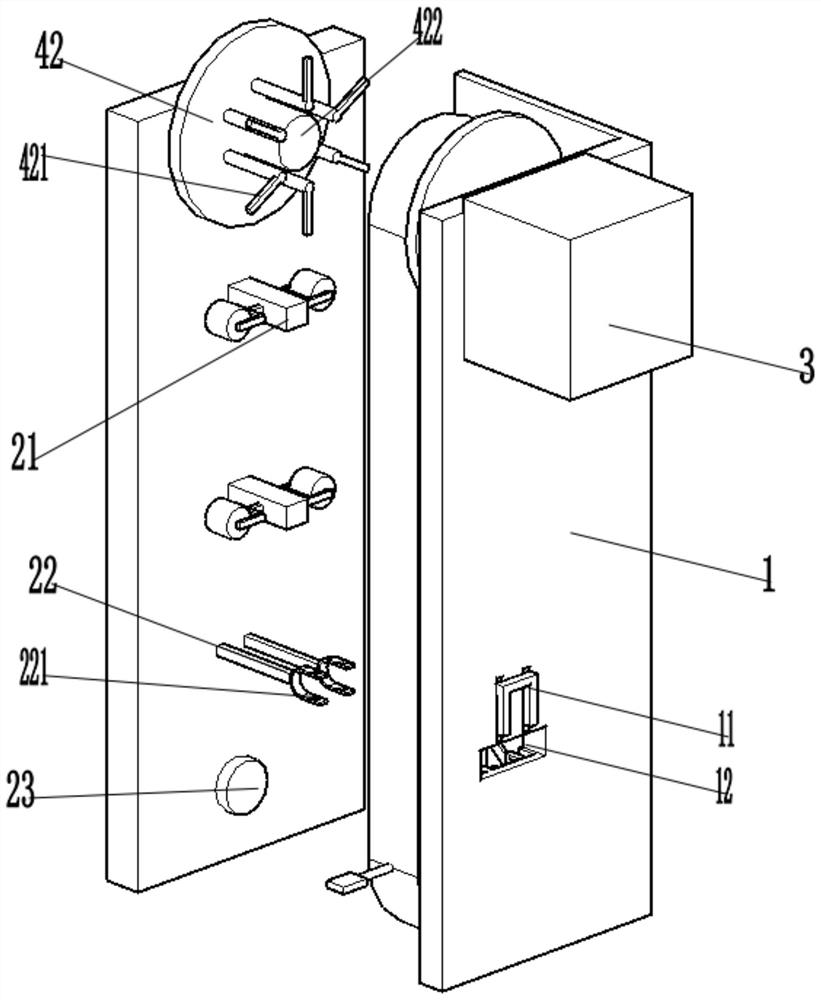
[0030] Such as Figure 1-Figure 2 As shown, the multi-rod lifting arm of the garment hanging system provided by the present invention includes: a main board 1, an auxiliary board 2, a motor 3, a driving wheel 4, a driven wheel 5, a transmission belt 6, and a displacement part 7;

[0031] Such as figure 1 As shown, the main board 1 is an "L"-shaped board, which is arranged opp...


PUM


Abstract

The invention relates to a garment hanging system, in particular to a multi-pull-rod type lifting arm of the garment hanging system. The multi-pull-rod type lifting arm of the garment hanging system comprises a main plate, a subplate, a motor, a driving wheel, a driven wheel, a driving belt and a displacement part, wherein the driving wheel is arranged on the top surface of the inner part of the main plate; the driven wheel and the driving wheels are correspondingly arranged up and down at a certain interval; the driving belt sleeves the driving wheel and the driven wheel; a push hook is arranged on the outer surface of the driving belt; the driving wheel is divided into a support part and a pulling part; a circular hole is formed in the middle of the support part; a support groove is formed in the surface, facing the pulling part, of the support part; and the lower part of the support groove is in a cylindrical shape. The invention aims to provide the multi-pull-rod type lifting arm of the garment hanging system, the complete driving belt can be arranged in a sleeving way without the need of being disassembled, and meanwhile, the driving belt is conveniently disassembled in a labor-saving way.

Description

technical field [0001] The invention relates to a garment hanging system, in particular to a multi-rod lifting arm of the garment hanging system. Background technique [0002] The garment hanging system is a device used for fabric sewing and garment making. The lifting arm is to lift the hanger roller holding the fabric from the working position to the ring rail longitudinally and lower it to the ring rail to facilitate subsequent processes. [0003] The lifting arm is connected to the transmission wheel through the motor. One of the two transmission wheels is active and the other is driven. The transmission wheel is covered with a transmission belt, and the outer side of the transmission belt is provided with a push rod. Under the action of the transmission belt, transmission wheel and motor, the hanger roller is pushed up. , due to the large span between the two drive wheels, when the push rod drives the hanger pulley to rise, the drive belt will be subjected to a reaction...

Claims


Application Information

Patent Timeline
Patent Type & Authority Patents(China)
IPC IPC(8): B65G35/06
CPCB65G35/06
Inventor 陈东海
Owner 衡阳腾飞内衣有限公司
Why Eureka
Try Eureka