Blast furnace cooling wall casing gas plugging device and working method

A technology for blocking devices and staves, applied in the direction of cooling devices, etc., can solve problems such as fatigue damage, high gas concentration, equipment damage, etc., and achieve the effect of long service life

Pending Publication Date: 2020-02-07
SD STEEL RIZHAO CO LTD
View PDF0 Cites 0 Cited by
  • Summary
  • Abstract
  • Description
  • Claims
  • Application Information

AI Technical Summary

Problems solved by technology

During the production process of the blast furnace, the temperature of the blast furnace shell is lowered by the circulation of water inside the stave, and the water pipe of the stave passes through the furnace shell, and the corrugated compensator is used to seal between the two. There is a relative displacement with the furnace body, and the corrugated compensator of the cooling water pipe is affected by temperature changes, and there is also a small amount of deformation displacement. Over time, it will be fatigued and damaged, resulting in gaps, which will eventually cause gas leakage in the furnace body. On the one hand, gas leakage is a safety hazard. On the other hand, the gas mixed with dust washes the cooling water pipe, causing equipment damage
Moreover, the concentration of gas in this part is high, and hot work cannot be carried out. It is difficult to deal with the leakage by the commonly used plugging methods, so it can only be dealt with by using the blast furnace shutdown machine.
[0003] There are generally two types of existing plugging methods: 1. Weld the leakage point; 2. Use ring-shaped steel plates to weld and seal the outer cover of the cooling water pipe corrugated compensator; the existing plugging methods cannot be operated in high-concentration gas environments. fire operation
Moreover, excessive welding repair cannot be performed when repairing the leakage point, otherwise the corrugated compensator will not be able to compensate
Due to the relative displacement between the cooling stave and the furnace body, the welding repair point maintains a short period of time to cause secondary leakage. The existing technology can only be repaired repeatedly, and cannot completely solve the problem of gas leakage.

Method used


Image

  • Blast furnace cooling wall casing gas plugging device and working method
  • Blast furnace cooling wall casing gas plugging device and working method

Examples


Embodiment Construction

[0021] The technical solutions in the embodiments of the present invention will be described clearly and completely in further detail below in conjunction with the accompanying drawings in the embodiments of the present invention. Based on the embodiments of the present invention, all other embodiments obtained by persons of ordinary skill in the art without making creative efforts belong to the protection scope of the present invention.

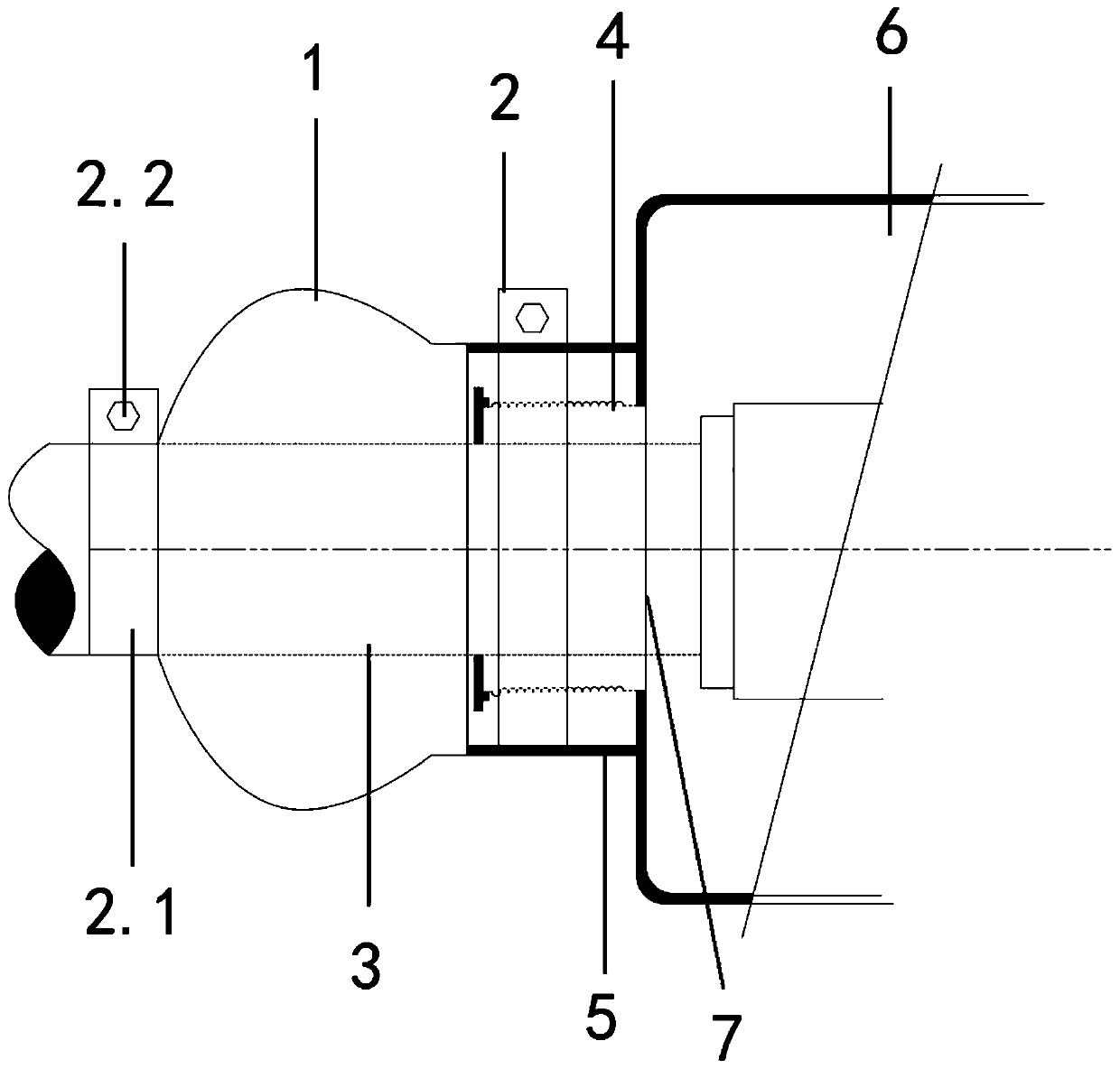
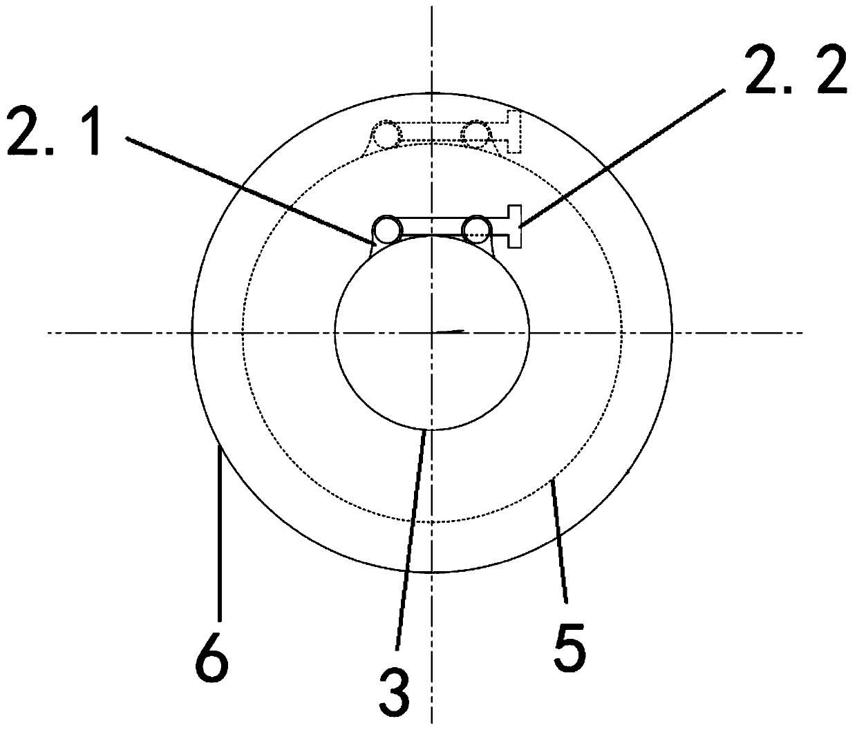
[0022] Such as Figure 1-2 As shown, a blast furnace stave casing gas blocking device includes a blast furnace 6, a cooling water pipe 3 extending into the inside of the blast furnace 6, and a corrugated compensator 4 connecting the blast furnace 6 and the cooling water pipe 3, and the cooling water pipe 3 passes through the blast furnace 6 The blast furnace wall 7 and the corrugated compensator 4 are sleeved on the cooling water pipe 3 , and one end of the corrugated compensator 4 is fixed on the blast furnace wall 7 for sealing the connect...


PUM


Abstract

The invention provides a blast furnace cooling wall casing gas plugging device and a working method. The blast furnace cooling wall casing gas plugging device comprises a blast furnace, a cooling water pipe extending into the interior of blast furnace as well as a ripple compensator connected with blast furnace and cooling water pipe, the cooling water pipe penetrates through the blast furnace wall of the blast furnace, the ripple compensator sleeves the cooling water pipe, and one end of the ripple compensator is fixed to the blast furnace wall so as to seal the joint between the cooling water pipe and the blast furnace wall; and the cooling water pipe is provided with a sealing part in a sleeve mode, one end of the sealing part is fixed to the cooling water pipe through the fixing part,and the other end of the sealing part is fixed to the ripple compensator through the fixing part and is used for forming an annular seal between the sealing part and the cooling water pipe. Accordingto the blast furnace cooling wall casing gas plugging device, leakage treatment of the blast furnace body is achieved under the condition of without fire, the designed sealing leather bag is long in service life through adopting the rubber material, the rubber material has flexibility, and the relative displacement between the cooling wall and the furnace body does not cause damage to the device.

Description

technical field [0001] The invention relates to the technical field of blast furnace maintenance, in particular to a blast furnace cooling wall casing gas plugging device and a working method. Background technique [0002] Casing gas leakage in cooling stave of blast furnace body is a relatively common abnormal phenomenon in blast furnaces in various ironworks. During the production process of the blast furnace, the temperature of the blast furnace shell is lowered by the circulation of water inside the stave, and the water pipe of the stave passes through the furnace shell, and the corrugated compensator is used to seal between the two. There is a relative displacement with the furnace body, and the corrugated compensator of the cooling water pipe is affected by temperature changes, and there is also a small amount of deformation displacement. Over time, it will be fatigued and damaged, resulting in gaps, which will eventually cause gas leakage in the furnace body. On the o...

Claims


Application Information

Patent Timeline
Patent Type & Authority Applications(China)
IPC IPC(8): C21B7/10
CPCC21B7/10
Inventor 亓玉敏白耀欢金龙刘志新赵莹超刘仁国李涛于亚生李庆洋王超许崇华
Owner SD STEEL RIZHAO CO LTD
Why Eureka
Try Eureka