Nacelle structure type lubricating oil tank

A lubricating oil tank, structural technology, applied in the direction of engine lubrication, turbine/propulsion device lubrication, engine components, etc., can solve the problems of difficult layout, oil tank rotor containment, heavy weight, etc., to save weight and space, reduce The effect of design difficulty

Active Publication Date: 2020-02-07
中航通飞华南飞机工业有限公司
View PDF5 Cites 1 Cited by
  • Summary
  • Abstract
  • Description
  • Claims
  • Application Information

AI Technical Summary

Problems solved by technology

[0002] The oil tank on the aircraft is generally provided by the engine, or a separate integrated fuel tank is set in the engine nacelle. The fuel tank is generally made of castings or welded parts, which has nothing to do with the structure of the engine nacelle, which has a large weight and space. The problem of waste, and the lubricating oil tank may face the problem of rotor containment, so the layout is difficult

Method used


Image

  • Nacelle structure type lubricating oil tank
  • Nacelle structure type lubricating oil tank
  • Nacelle structure type lubricating oil tank

Examples


Embodiment Construction

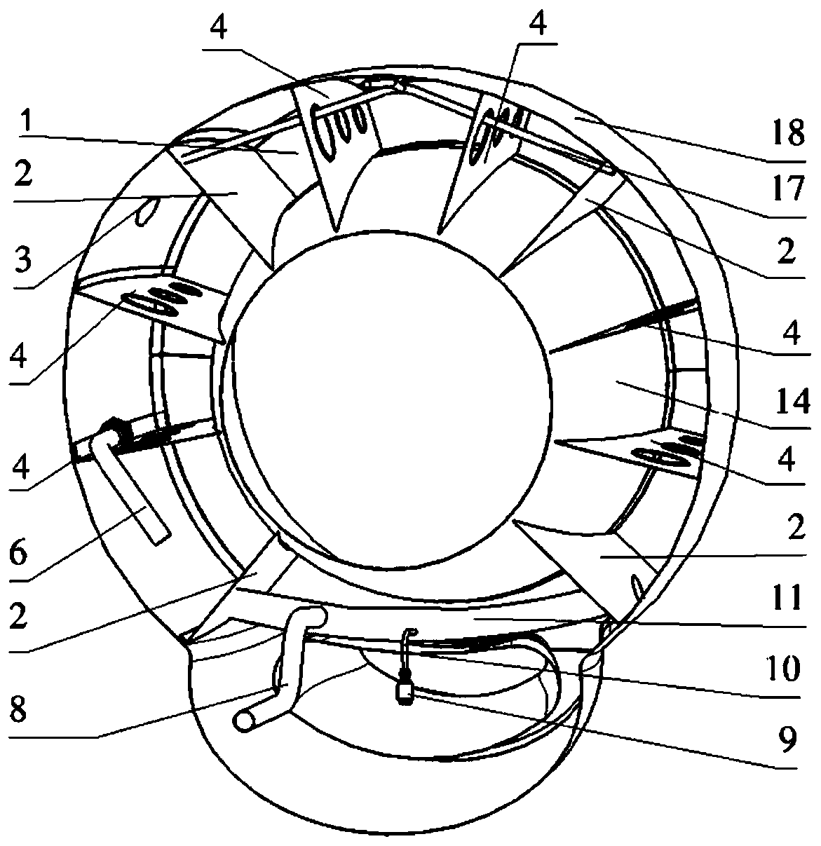
[0021] In practical applications, the integrated lubricating oil tank is located in the designated fire zone of the aircraft, and the design requirements are high and difficult. In the front of the engine nacelle, since the reducer of the engine is usually relatively small in size, there is a large space between the engine and the nacelle skin, which will not be affected by the rotor. This area does not belong to the designated fire zone. No structural oil tank is designed in the engine nacelle.

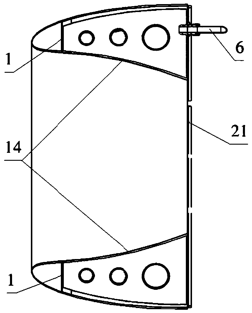
[0022] When lubricating oil is added through the filling port 3, the lubricating oil enters the lubricating oil tank, and the left and right sides are kept refueling at the same time through the connecting pipe 11 and the vent pipe 17, and the liquid level is consistent;

[0023] The gap provided on the edge of the support partition 4 should be located at the bottom to prevent the occurrence of dead oil; Riveted and glued.

[0024] The diameter of the connecting pipe 11 should not ...


PUM


Abstract

The invention provides a nacelle structure lubricating oil tank. The lubricating oil tank comprises a shell, an oil filling port, an oil supply pipe, a feathering oil supply pipe, a discharging valve,a discharging pipe, a communicating pipe, a breather pipe and a rear wall plate. The shell comprises a rear wall plate, a front wall plate, an inner skin, an outer skin and at least two sealing partitions. The at least two sealing partitions are arranged in an annular cavity enclosed by the rear wall plate, the front wall plate, the inner skin and the outer skin. At least two support partitions are arranged between the outer skin and the inner skin. The oil filling port is formed in the upper portion of the outer skin. The two sealing partitions below the outer skin are connected through thecommunicating pipe. The feathering oil supply pipe and the discharging pipe are arranged on the communicating pipe. The feathering oil supply pipe is connected with the aircraft feathering oil supplypipeline. The discharging pipe is located at the bottom of the communicating pipe. The discharging valve is arranged at the bottom of the discharging pipe. The oil supply pipe is arranged in the middle of the rear wall plate. The breather pipe is communicated with the left side and the right side of the lubricating oil tank.

Description

technical field [0001] The invention belongs to the field of aircraft structure design, and relates to a nacelle structure lubricating oil tank, in particular, the functions of refueling, oil storage, oil supply and oil discharge can be realized by utilizing the space of the nacelle structure. Background technique [0002] The oil tank on the aircraft is generally provided by the engine, or a separate integrated fuel tank is set in the engine nacelle. The fuel tank is generally made of castings or welded parts, and has nothing to do with the structure of the engine nacelle, which has a large weight and space. The problem of waste, and the lubricating oil tank may face the problem of rotor containment, so the layout is difficult. Contents of the invention [0003] The invention provides a lubricating oil tank with a nacelle structure, which has the functions of refueling, oil storage, oil supply and oil discharge, can rationally utilize the space of the nacelle, and store l...

Claims


Application Information

Patent Timeline
Patent Type & Authority Applications(China)
IPC IPC(8): F02C7/06
CPCF02C7/06
Inventor 翟冰冰李符建田傲张庆江声兰邢芳芳
Owner 中航通飞华南飞机工业有限公司
Why Eureka
Try Eureka