Trapezoidal panel pin joint allowing free deflection between fuselage and wing

a technology of fuselage and pin joint, which is applied in the direction of fuselage, aircraft floors, transportation and packaging, etc., can solve the problems of increasing the risk of durability of parts, affecting the design and durability of pin joints, and causing stress on wing and fuselage, so as to reduce the significant weight and significant durability risk, improve the design of pin joints, and reduce the effect of induced stress

Active Publication Date: 2009-06-16
THE BOEING CO
View PDF11 Cites 20 Cited by
  • Summary
  • Abstract
  • Description
  • Claims
  • Application Information

AI Technical Summary

Benefits of technology

[0006]The invention satisfies this need for an improved pin joint design in an aircraft fuselage. None of the known pin joint designs provides all of the numerous advantages of the invention. Unlike known designs, the design of the invention provides the following advantages: the trapezoidal panel pin joint design reduces significant weight and significant risk of durability issues in service; the trapezoidal panel pin joint design alleviates the induced stresses by allowing free rotation at the upper surface of the wing aft spar by use of a vertically oriented pin and vertical and horizontal flexible tee members allowing an added degree of freedom, and thus, the design of the invention releases two rotational degrees of freedom; the trapezoidal panel pin joint design allows a high deflection in a localized area and then uses flexible attachments a short distance away from the flexible joint; the trapezoidal panel pin joint and flexible tee members reduce induced loading from wing bending and allow the overwing joint to flex with wing deflection and fuselage pressurization; the trapezoidal panel pin joint design allows a trapezoidal panel to be able to handle wing deflections without inducing high loads into the joint; the trapezoidal panel pin joint design allows the fixed pressure deck and floor beams to be located in close proximity to the wing upper surface on a composite or metal aircraft without inducing high deflections or point loads into the aircraft fuselage, and thus enables efficient space utilization by locating the fixed pressure deck and wing upper surface in close proximity to each other; and, the trapezoidal panel pin joint design allows weight and space saving within the composite structure architecture of an aircraft.
[0007]The disclosure provides for a trapezoidal panel pin joint to allow deflection of an aircraft between a fuselage section and a wing section, the pin joint comprising a vertical pin portion, a lug portion, and a clevis portion, and the pin joint is positioned at a wing rear spar of the aircraft. At least one vertical flexible tee member is positioned below the pin joint. The pin joint is coupled to at least two horizontal flexible tee members, such that the pin joint and the vertical flexible tee member allow for vertical rotation at the wing rear spar, and such that the horizontal flexible tee members allow for horizontal rotation at a wing / fuselage joint. Preferably, the vertical flexible tee member has a vertical flexible rabbet within the member, and the horizontal flexible tee member has a horizontal flexible rabbet within the member. The pin joint allows a trapezoidal panel of the fuselage section to be able to handle deflections in the wing section without inducing high loads into the joint. In another aspect of the disclosure, the disclosure provides for a flexible fuselage point to enable deflection of an aircraft without high strain comprising a panel pin joint and flexible tee members that, in combination, allow a wing / fuselage joint to rotate with wing deflection and fuselage pressurization, in conjunction with a vertical degree of rotation at a wing rear spar.

Problems solved by technology

In aircraft, large deflections between the wing and the fuselage due to wing bending can cause design and durability problems in the fuselage and fuselage to wing attachment structure.
However, such known designs can have less vertical distance to incur the large wing deflections, and this can induce stresses to the wing and fuselage.
This can increase the risk of durability of the parts, can require more structure, and can increase the weight of the aircraft.
In addition, known designs only release one rotational degree of freedom.

Method used


Image

  • Trapezoidal panel pin joint allowing free deflection between fuselage and wing
  • Trapezoidal panel pin joint allowing free deflection between fuselage and wing
  • Trapezoidal panel pin joint allowing free deflection between fuselage and wing

Examples


Embodiment Construction

[0014]The invention now will be described more fully hereinafter with reference to the accompanying drawings, in which some, but not all embodiments of the invention are shown. Indeed, this invention may be embodied in several different forms and should not be construed as limited to the embodiments set forth herein. Rather, these embodiments are provided so that this disclosure will be thorough and complete and will fully convey the scope of the invention to those skilled in the art. Like numbers refer to like elements throughout.

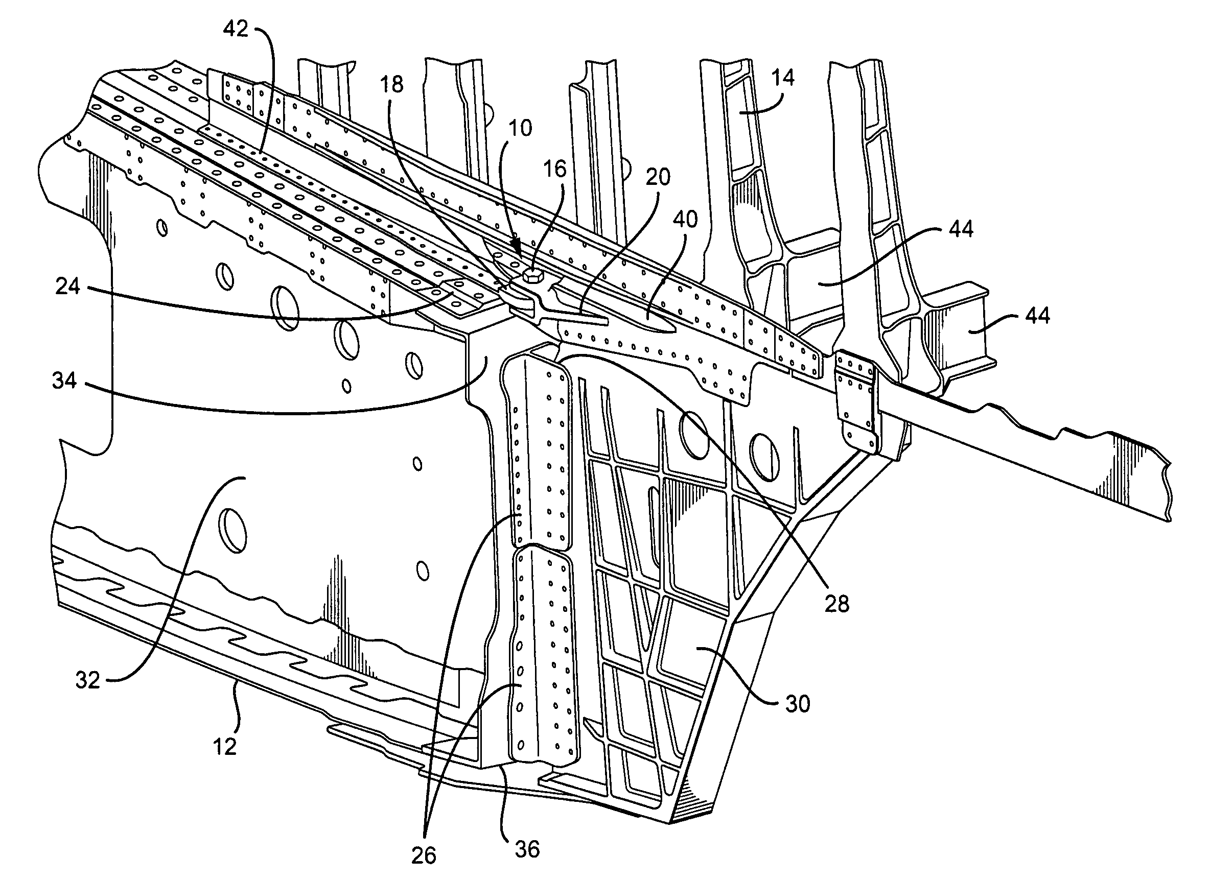
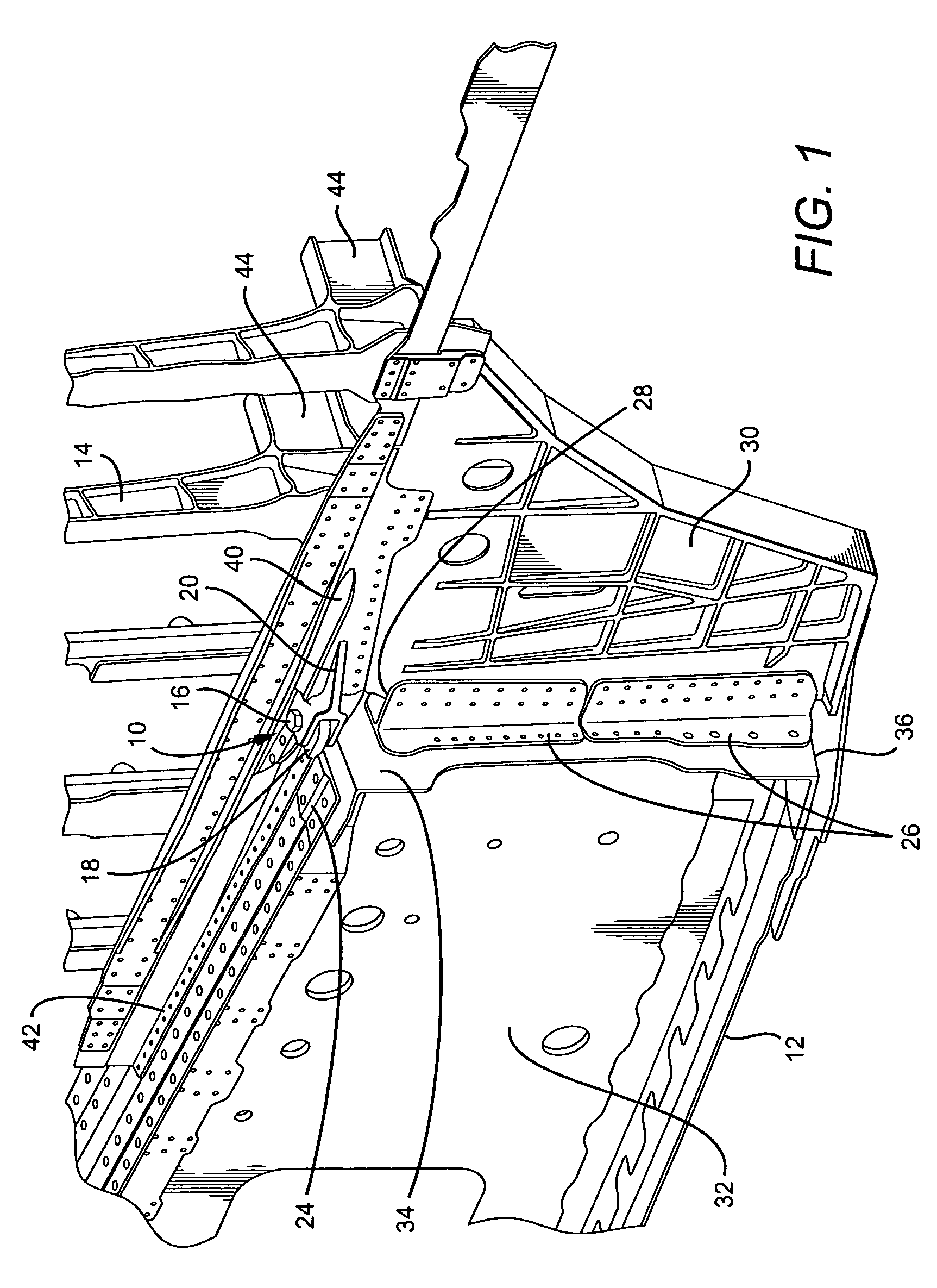
[0015]Referring now to the drawings, and in particular, to FIG. 1, there is shown a perspective view illustrating a trapezoidal panel pin joint 10 of the invention engaged with a wing portion 12 and a fuselage or body portion 14 of an aircraft. Preferably, the invention is used with large commercial aircraft. However, the invention may also be used with noncommercial aircraft. The pin joint 10 preferably comprises a vertical pin portion 16, a lug portion 1...


PUM


Abstract

The invention is directed a trapezoidal panel pin joint for allowing deflection of an aircraft between a fuselage section and a wing section, wherein the pin joint comprises a vertical pin portion, a lug portion, and a clevis portion; wherein at least one vertical flexible tee member is positioned below the pin joint; and wherein the pin joint is coupled to at least two horizontal flexible tee members, such that the pin joint and vertical and horizontal flexible tee members, in combination, release two rotational degrees of freedom.

Description

BACKGROUND OF THE INVENTION[0001]1) Field of the Invention[0002]The invention relates to a pin joint in an aircraft fuselage. More particularly, the invention relates to a trapezoidal panel pin joint allowing free deflection between the fuselage and the wing of an aircraft.[0003]2) Description of Related Art[0004]In aircraft, large deflections between the wing and the fuselage due to wing bending can cause design and durability problems in the fuselage and fuselage to wing attachment structure. Known aircraft have wing to fuselage attachment structure that have accounted for this differential deflection by separating the top of the wing box and the fuselage with a horizontal flexible tee member. Known aircraft have a trapezoidal panel that is an extension of the wing rib at the wing / fuselage joint. Known trapezoidal panel designs have accounted for the differential deflection between the wing and the fuselage / fixed pressure deck by vertically separating the trapezoidal panel and fix...

Claims


Application Information

Patent Timeline
Patent Type & Authority Patents(United States)
IPC IPC(8): B64C1/00
CPCB64C1/26
Inventor ESTELL, PATRICIA W.POLK, JOHN H.
Owner THE BOEING CO
Why Eureka
Try Eureka